Shunt valve for controlling siphon effect

a shunt valve and siphon effect technology, applied in the field of surgical implanted delivery and drainage catheters, can solve the problems of excessive fluid flow through such a shunt system, preventing adequate fluid flow, and fluid flow, so as to prevent tissue ingrowth into pores and prevent adverse mechanical influence of overlying body tissu

Active Publication Date: 2013-08-22
WATSON DAVID A
View PDF2 Cites 3 Cited by
  • Summary
  • Abstract
  • Description
  • Claims
  • Application Information

AI Technical Summary

Benefits of technology

[0016]The present invention also provides for an apparatus for preventing an adverse mechanical influence of overlying body tissue on an implantable mechanism having active surfaces. The apparatus includes a porous membrane displaced from and overlying the implantable mechanism, the porous membrane being configured to prevent direct contact of the body tissue with any active surfaces of the implantable mechanism, and a fluid filled space provided between the porous membrane and the implantable mechanism. In a presently preferred aspect, the fluid-filled spac

Problems solved by technology

However, excessive fluid flow through such a shunt system can occur due to a siphoning effect of hydrostatic pressure, such as can be created by the elevation of the proximal catheter inlet with respect to the distal catheter outlet such as when a shunted patient is upright.
However, it has been found that the flexible, elastic diaphragms that are configured on the outer surface of the valve can be forced shut, preventing adequate fluid flow, or can become distorted, allowing excess fluid flow through the siphon control device due to external mechanical tissue pressures.
An

Method used


Image

  • Shunt valve for controlling siphon effect
  • Shunt valve for controlling siphon effect

Examples


Embodiment Construction

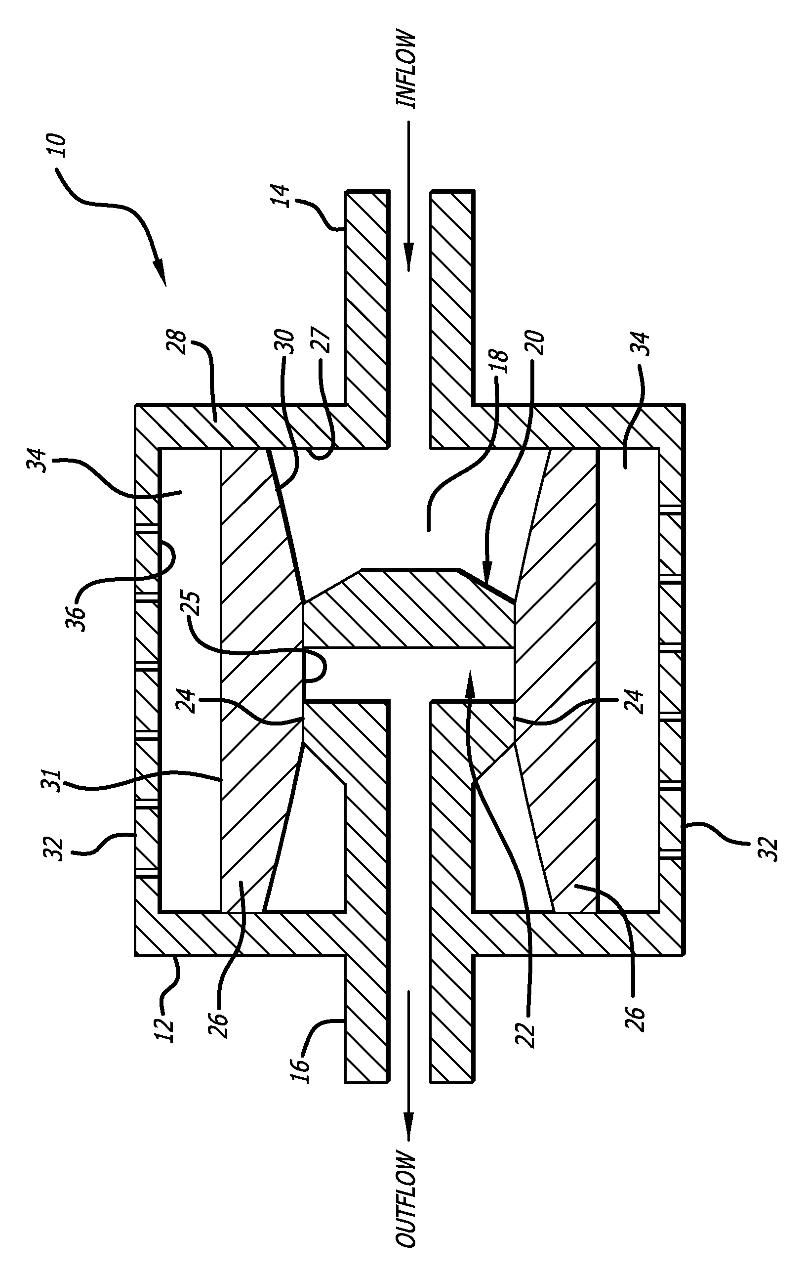
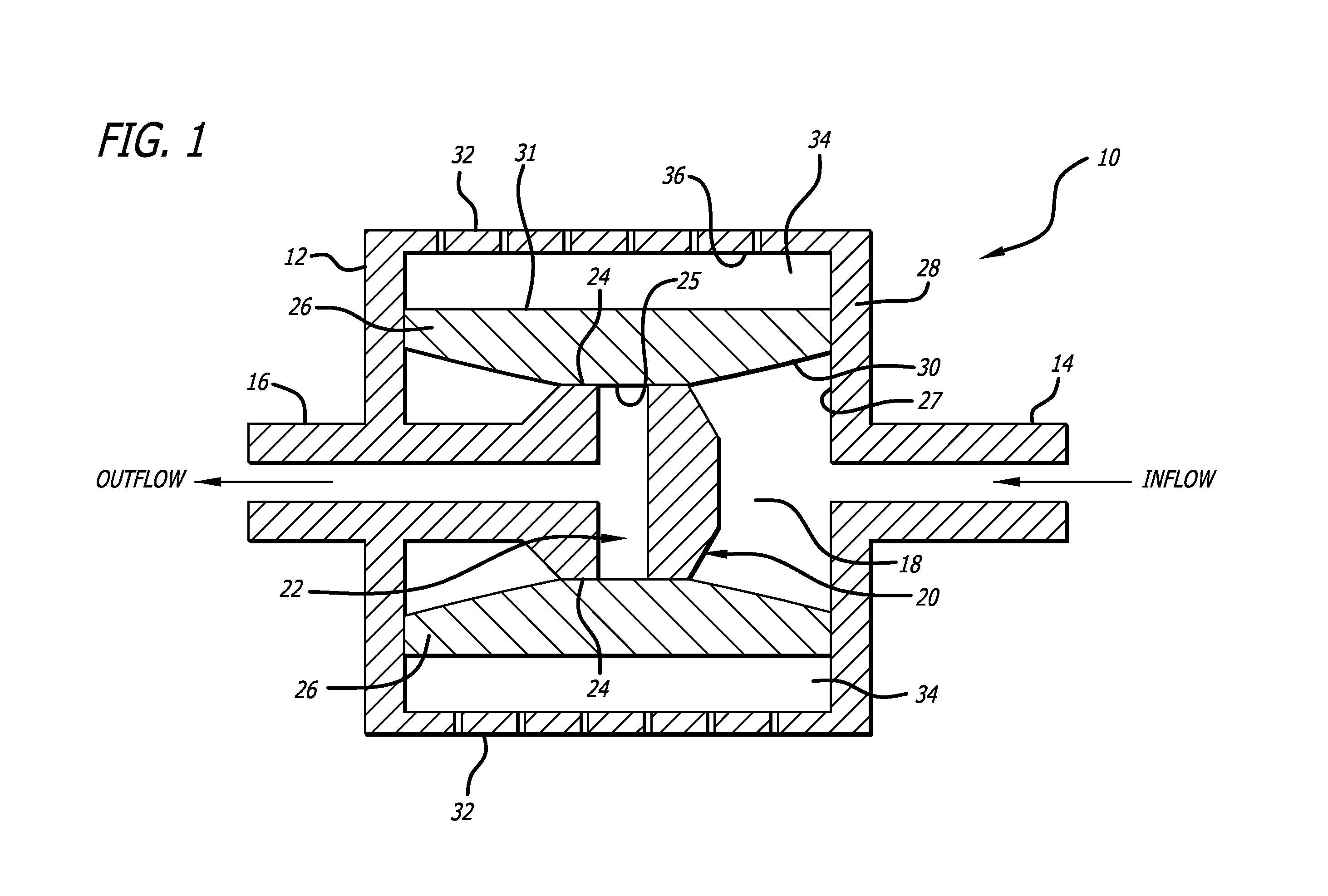
[0019]Referring to the drawings, which are provided by way of example, and not by way of limitation, the present invention provides for a valve such as a shunt valve 10 adapted to be surgically implanted in a tissue space of a body of a mammal for draining fluid from one portion of the body to another for controlling hydrostatic siphon effect, to prevent excessive drainage which may be caused by the siphoning effect of hydrostatic pressure in a distal shunt catheter (not shown).

[0020]The valve includes a housing 12, formed to have a shape of a disc when viewed from the top or bottom, for example, although the housing can also be configured to have a cylindrical shape when viewed from the top or bottom. The valve includes an inlet connector 14 configured to be connected to an proximal catheter (not shown) such as surgical tubing or a ventricular catheter, and an outlet connector 16 configured to be connected to a distal catheter (not shown) such as surgical tubing or a peritoneal cat...


PUM


Abstract

An improved shunt valve for the control of hydrocephalus provides for physiological atmospherically-referenced siphon control that is not adversely affected by overlying tissue. The valve includes one or more porous outer anti-fouling membranes to protect the flow control membranes from external mechanical tissue pressure, while permitting free movement of the flow control moveable membranes and permitting positive inlet pressure to regulate flow through the improved fluid shunt valve of the invention. The porous membranes are configured to prevent tissue ingrowth into the membranes pores while allowing adequate fluid flow across so as not to inhibit movement of the movable membrane.

Description

CROSS-REFERENCES TO RELATED APPLICATIONS[0001]This application is based upon and claims priority from Provisional Application No. 61 / 598,248, filed Feb. 13, 2012, incorporated by reference herein.BACKGROUND OF THE INVENTION[0002]This invention relates generally to surgically implanted delivery and drainage catheters, such as in shunt systems that drain cerebrospinal fluid from the brain ventricles and pressure sensors implanted in fluid filled spaces or within the parenchyma of tissues. More particularly, this invention relates to an improved shunt valve including outer porous anti-fouling membranes that protect movable siphon control membranes of the shunt from external mechanical pressures. The invention also provides for a means for preventing the mechanical influence of overlying tissue from affecting the accuracy of indwelling pressure sensors.[0003]In order to relieve undesirable accumulation of body fluids it is frequently necessary to provide a shunt for controlled drainage ...

Claims


Application Information

Patent Timeline
IPC IPC(8): A61M27/00A61B17/00
CPCA61B17/00A61M27/006
Inventor WATSON, DAVID A.
Owner WATSON DAVID A
Why Eureka
Try Eureka