

Solar thermal receiver with concentric tube modules
a solar thermal and receiver technology, applied in solar heat systems, solar thermal energy generation, lighting and heating apparatus, etc., can solve the problems of complex drainage procedures, added costs, and additional part counts, and achieve low pressure drop, good heat transfer coefficient, and adequate receiver characteristics.
- Summary
- Abstract
- Description
- Claims
- Application Information
AI Technical Summary
Benefits of technology
Problems solved by technology
Method used
Image

Examples
Embodiment Construction
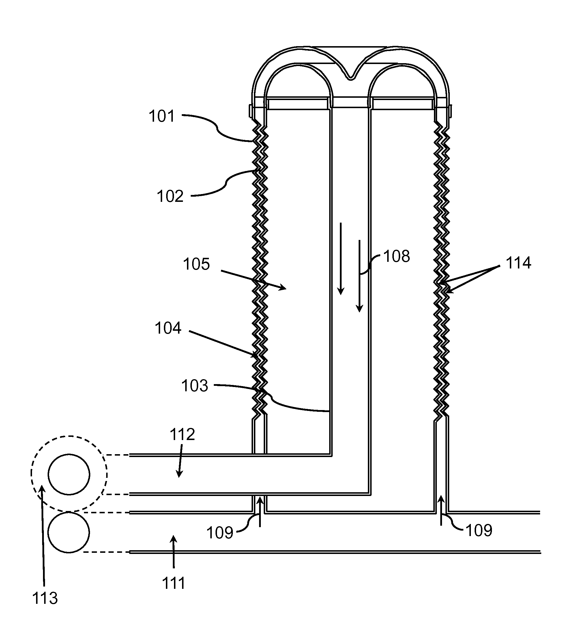
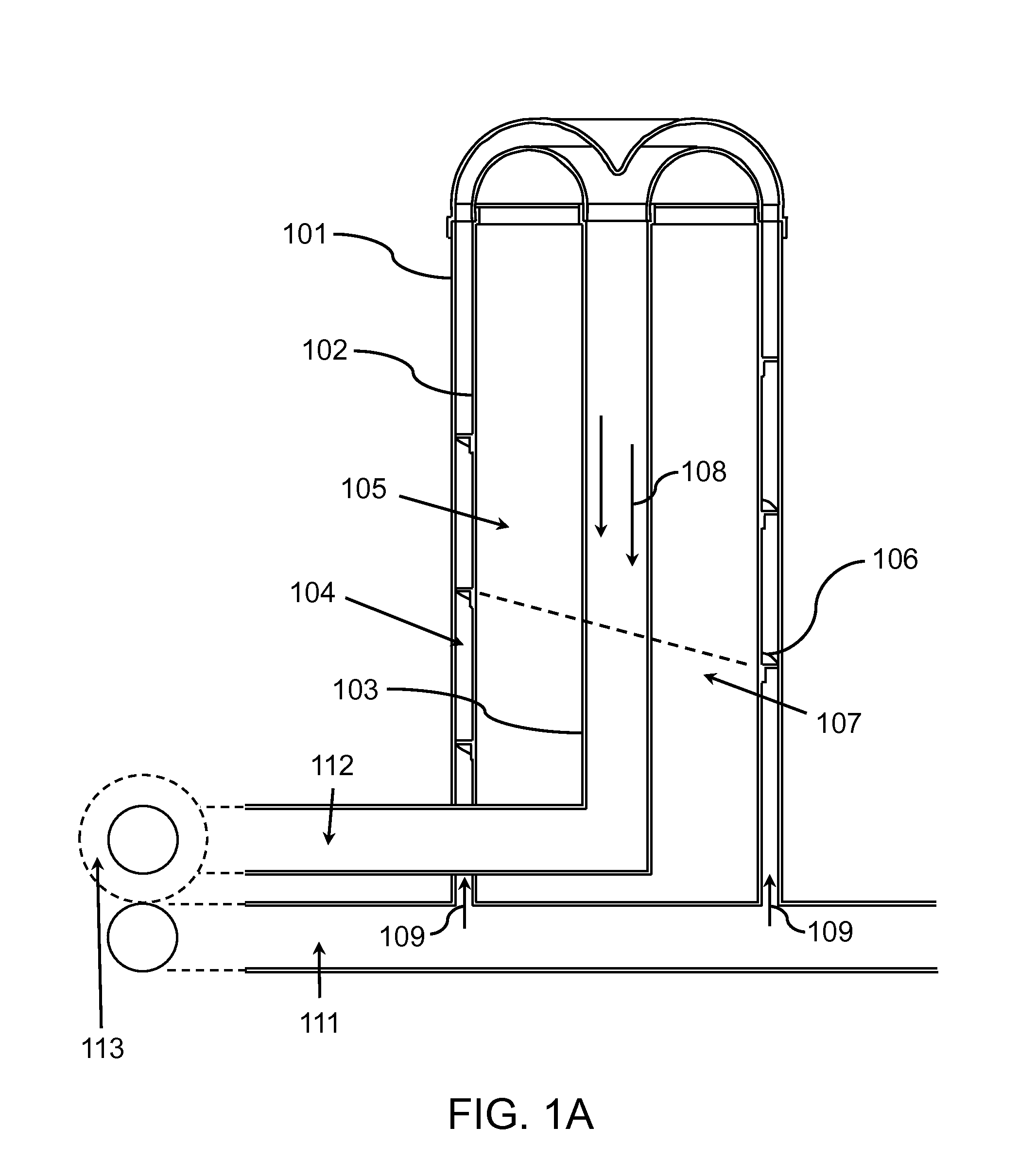
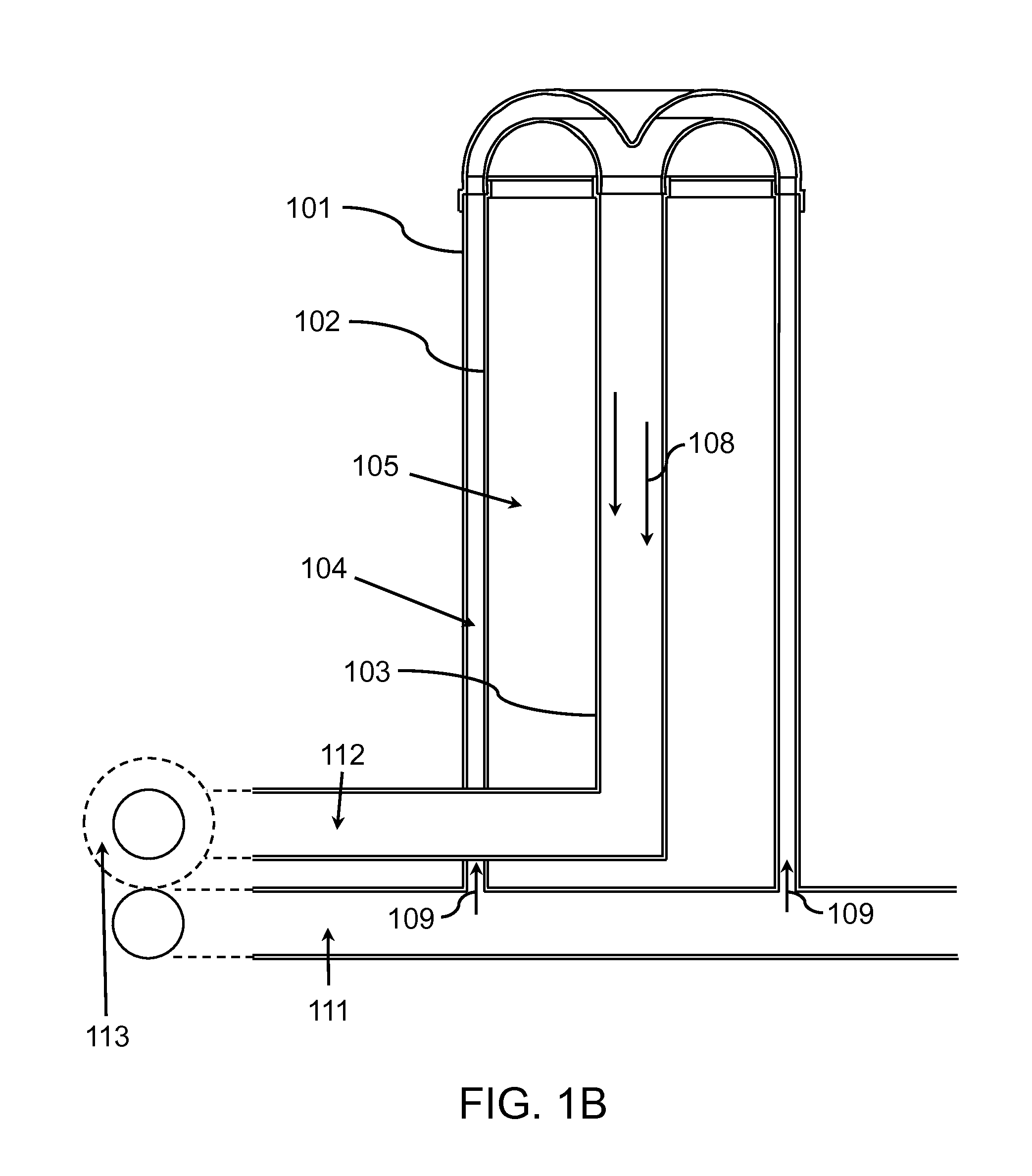
[0023]FIG. 1A depicts an exemplary module of an exemplary solar thermal receiver embodiment comprising three concentric tubes of different diameters: a first outer tube 101, a second inner tube 102, and a third central tube 103. The first tube 101 and second tube 102 have a small diameter difference compared to their respective diameters, allowing for an annular gap 104 between the first tube 101 and the second tube 102. The dimensions of the annular gap 104 may be determined based on the pressure drop and heat transfer coefficient between a heat transfer fluid (HTF) and the absorbed flux. In addition, the receiver module outside diameter may be determined based on these latter two characteristics as well as the structural integrity of the receiver module. The larger the receiver diameter, the more it may be rigid and self-supported. There may be a greater diameter difference between the second tube 102 and the third tube 103 than the first tube 101 and the second tube 102, providin...
PUM
 Abstract
Description
Claims
Application Information