Self-cleaning fluidized bed heat exchanger

A fluidized bed heat exchanger and self-cleaning technology, applied in fluidized bed heat exchangers, indirect heat exchangers, heat exchanger types, etc., can solve the problem of decreased heat exchange effect and easy scaling of the heat exchanger tube And other issues

Active Publication Date: 2019-04-12
CHINA PETROLEUM & CHEM CORP +1
View PDF8 Cites 0 Cited by
  • Summary
  • Abstract
  • Description
  • Claims
  • Application Information

AI Technical Summary

Problems solved by technology

[0006] The technical problem to be solved by the present invention is that in the prior art, the tube side of the heat exchanger is prone to fouling, and the heat exchange effect is obviously reduced after long-term use. A self-cleaning fluidized bed heat exchanger is provided

Method used


Image

  • Self-cleaning fluidized bed heat exchanger
  • Self-cleaning fluidized bed heat exchanger
  • Self-cleaning fluidized bed heat exchanger

Examples


Embodiment 1

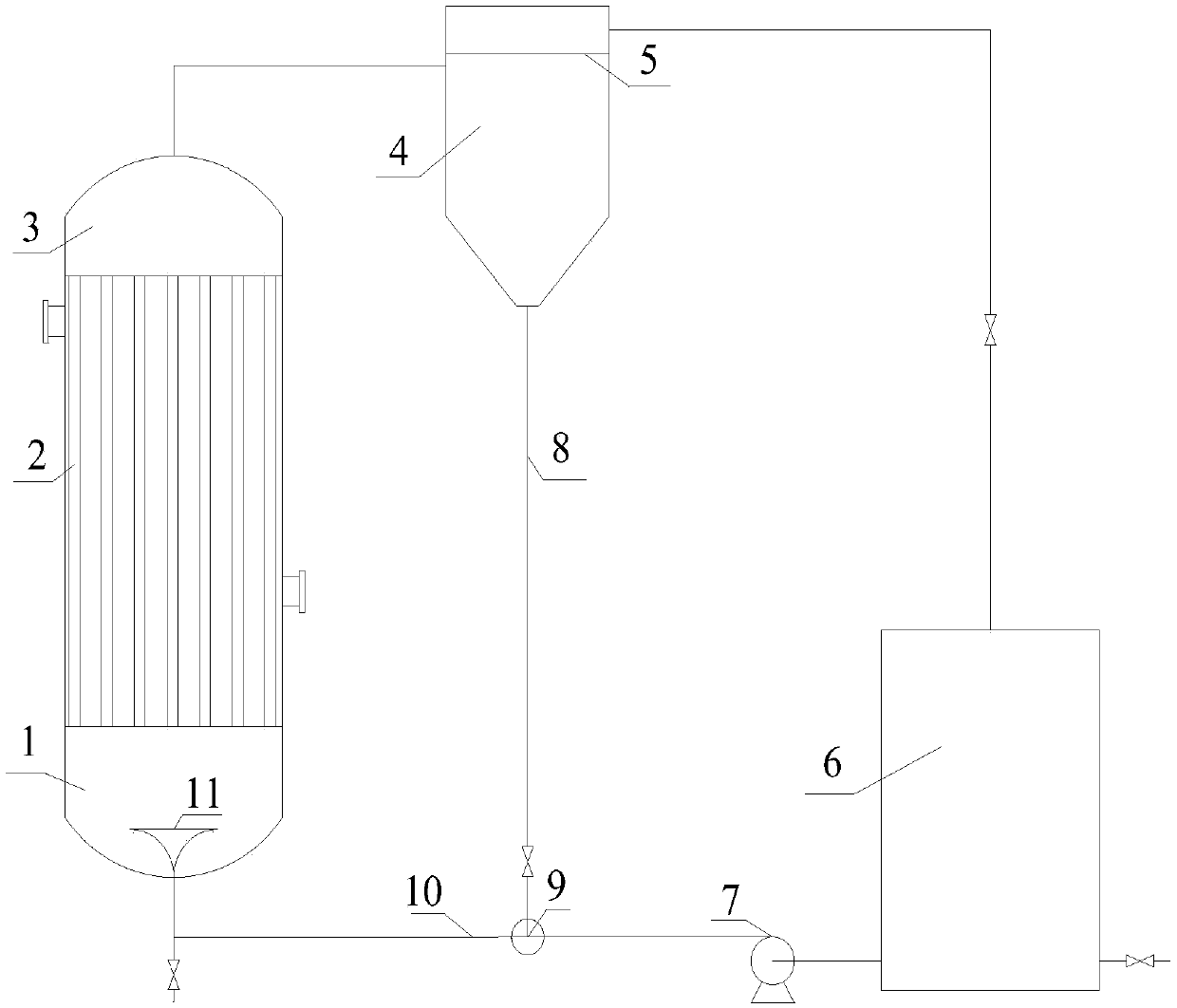
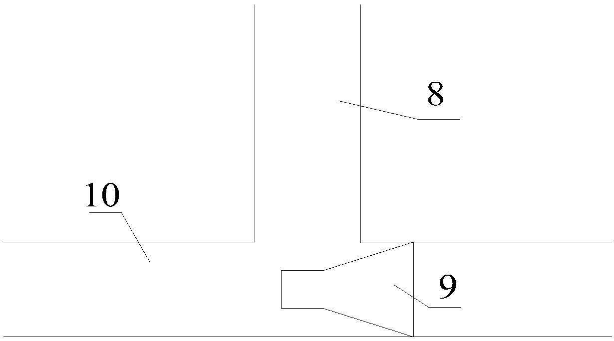
[0028] use figure 1 The self-cleaning fluidized bed heat exchanger shown is applied to the lye cooler of the decarburization system of a synthetic ammonia plant. The self-cleaning fluidized bed heat exchanger is equipped with 588 heat exchanger tubes, each tube is 4500mm long, and the tube The diameter is Φ22×1.5mm, arranged in an equilateral triangle, the diameter of the horizontal pipe is 200mm, and the diameter of the descending pipe is 100mm. The solid particles are glass beads with an average particle diameter of 5mm, and the average volume solid content of the solid particles in the self-cleaning fluidized bed heat exchanger is 3%. The circulating water flow rate is 1m / s. The liquid-solid separator adopts the gravity sedimentation type. The diameter of the expansion port is 600mm, and the height is 300mm. It is a swirling flow distributor with 3 rotating vanes inside. The cross-section of the small mouth of the nozzle is aligned with the centerline of the downcomer, a...

Embodiment 2~16

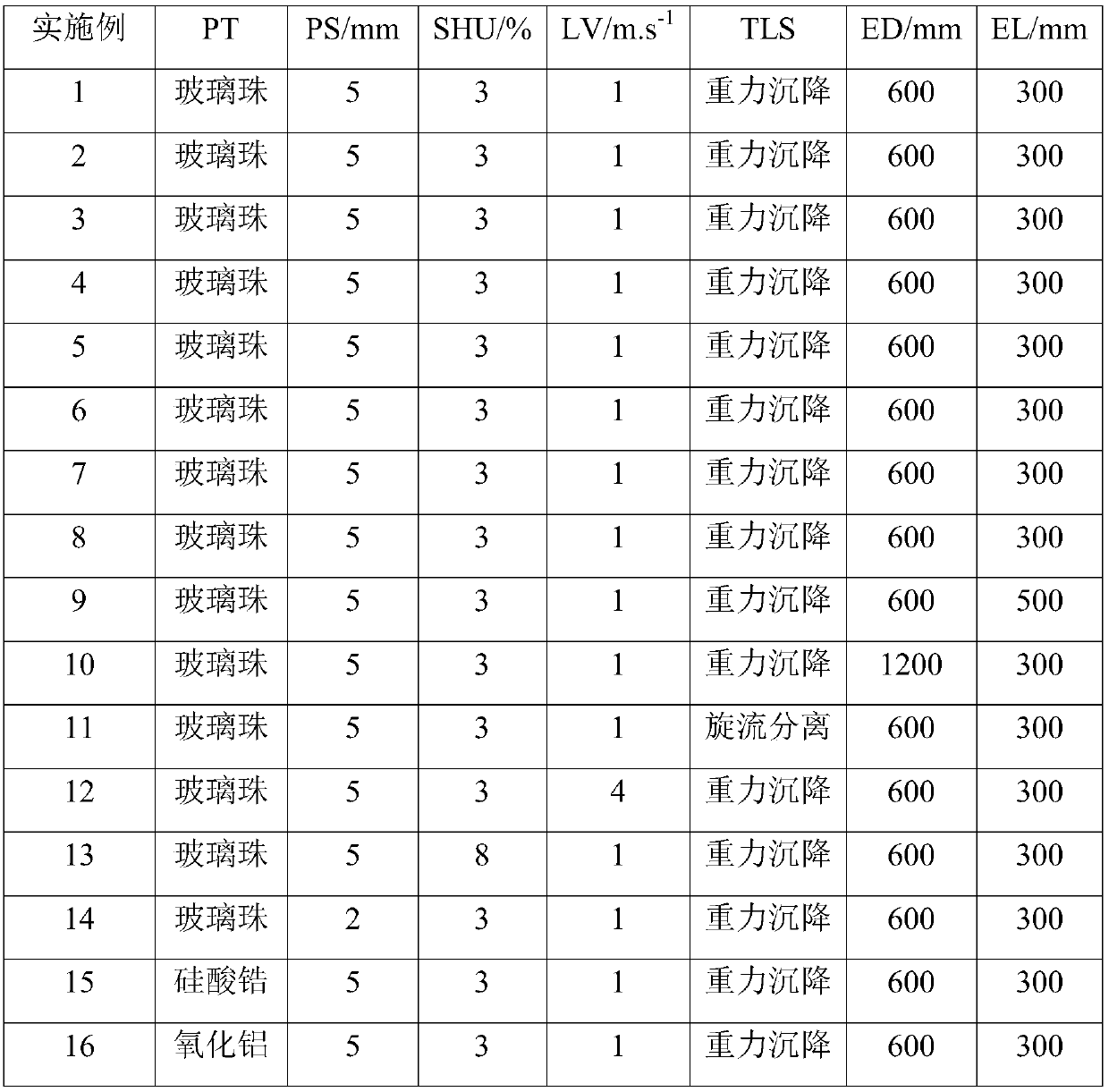
[0030] The same self-cleaning fluidized bed heat exchanger as in Example 1 is applied to the lye cooler of the decarburization system of a synthetic ammonia plant. The self-cleaning fluidized bed heat exchanger is equipped with 588 heat exchanger tubes, and each tube The length is 4500mm, the pipe diameter is Φ22×1.5mm, arranged in an equilateral triangle, the diameter of the horizontal pipe is 200mm, and the diameter of the descending pipe is 100mm. Change the solid particle type (PT), solid particle average particle size (PS), solid particle average volume solids rate (SHU) in the self-cleaning fluidized bed heat exchanger, circulating water flow rate (LV), liquid-solid separator Type (TLS), diameter of the expansion port (ED), height of the expansion port (EL), number of swirl distributor blades in the expansion port (EN), speed of the expansion port (ER), cross-section of the large port of the expansion port The distance (EH) to the lower end section of the heat exchanger ...


PUM


Abstract

The invention relates to a self-cleaning fluidized bed heat exchanger which is mainly used for solving the technical problems that in the prior art, the tube pass of a decarburization alkaline liquorcooler of an ammonia synthesizing device is prone to scaling, and the heat exchange effect is obviously decreased after long-period use. The self-cleaning fluidized bed heat exchanger comprises a lower tube box 1, a heat exchanger tube nest 2, an upper tube box 3, a liquid-solid separator 4, a particle filtering plate 5, a liquid storing tank 6, a liquid circulating pump 7, a downcomer 8, a spraynozzle 9, a horizontal pipe 10 and an expanding port 11, wherein the expanding port 11 is installed in the lower tube box 1, the upper tube box 3 is connected with the liquid-solid separator 4, solidparticles enter the spray nozzle 9 through the downcomer 8, and a liquid phase overflows from the upper portion of the particle filtering plate 5, enters the liquid storing tank 6 and circulates to the spray nozzle 9 through the liquid circulating pump 7. According to the technical scheme, the technical problems are well solved, and the self-cleaning fluidized bed heat exchanger can be used for prolonging the running cycle of the decarburization alkaline liquor cooler of the ammonia synthesizing device.

Description

technical field [0001] The invention belongs to the field of chemical industry, specifically, belongs to the field of long-term operation of chemical heat exchange equipment, and relates to a self-cleaning fluidized bed heat exchanger, which is widely used to solve the problem of liquid phase leakage in the tube side, and the tube side is prone to fouling and blockage Long-term operation problems of vertical shell and tube heat exchangers. Background technique [0002] Heat exchangers are widely used in petroleum, chemical, energy and other industries. However, as the use time increases, there will inevitably be dirt adhesion in the heat exchanger, which will reduce the heat exchange efficiency of the heat exchanger and increase the resistance, which will affect the normal operation of the heat exchanger. [0003] The development of a self-cleaning fluidized bed heat exchanger to replace the traditional heat exchanger can improve the heat transfer effect of the heat exchang...

Claims


Application Information

Patent Timeline
Patent Type & Authority Patents(China)
IPC IPC(8): F28D13/00F28G9/00
CPCF28D13/00F28G9/00
Inventor 顾军民田立达张斌
Owner CHINA PETROLEUM & CHEM CORP
Why Eureka
Try Eureka