Efficient temperature forcing of semiconductor devices under test

a technology of temperature forcing and semiconductor devices, applied in the field of temperature forcing of semiconductor chips and modules, can solve the problems of insufficient temperature raising of the casing, large cumulative temperature differential, and exothermic process of the dut, and achieve the effect of improving the temperature forcing process, reducing device temperature, and increasing thermal efficiency

a technology of temperature forcing and semiconductor devices, applied in the field of temperature forcing of semiconductor chips and modules, can solve the problems of insufficient temperature raising of the casing, large cumulative temperature differential, and exothermic process of the dut, and achieve the effect of improving the temperature forcing process, reducing device temperature, and increasing thermal efficiency

US20130220579A1Active Publication Date: 2013-08-29M D MECHANICAL DEVICES +2

Image

  • Efficient temperature forcing of semiconductor devices under test
  • Efficient temperature forcing of semiconductor devices under test
  • Efficient temperature forcing of semiconductor devices under test

Examples


Embodiment Construction

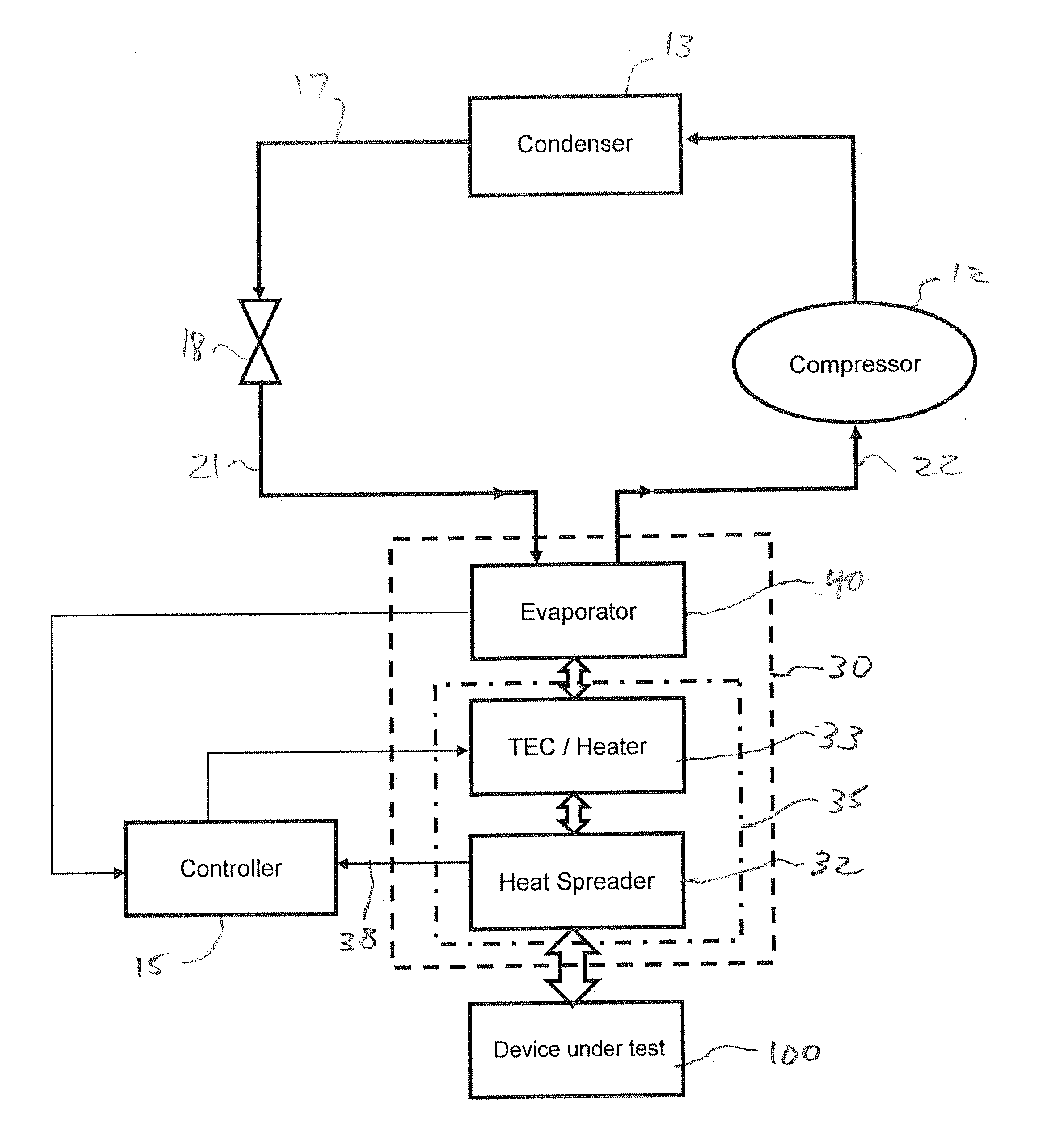
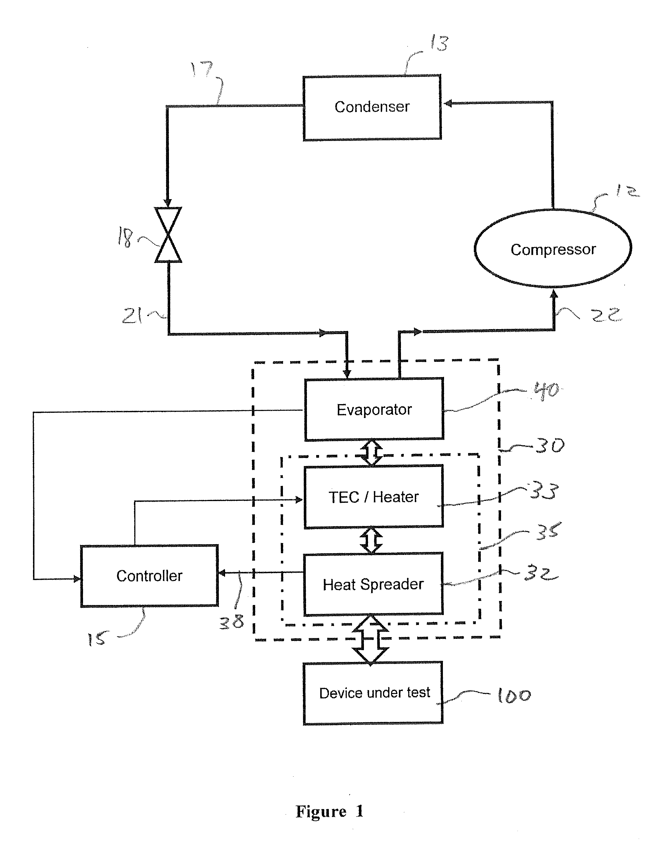
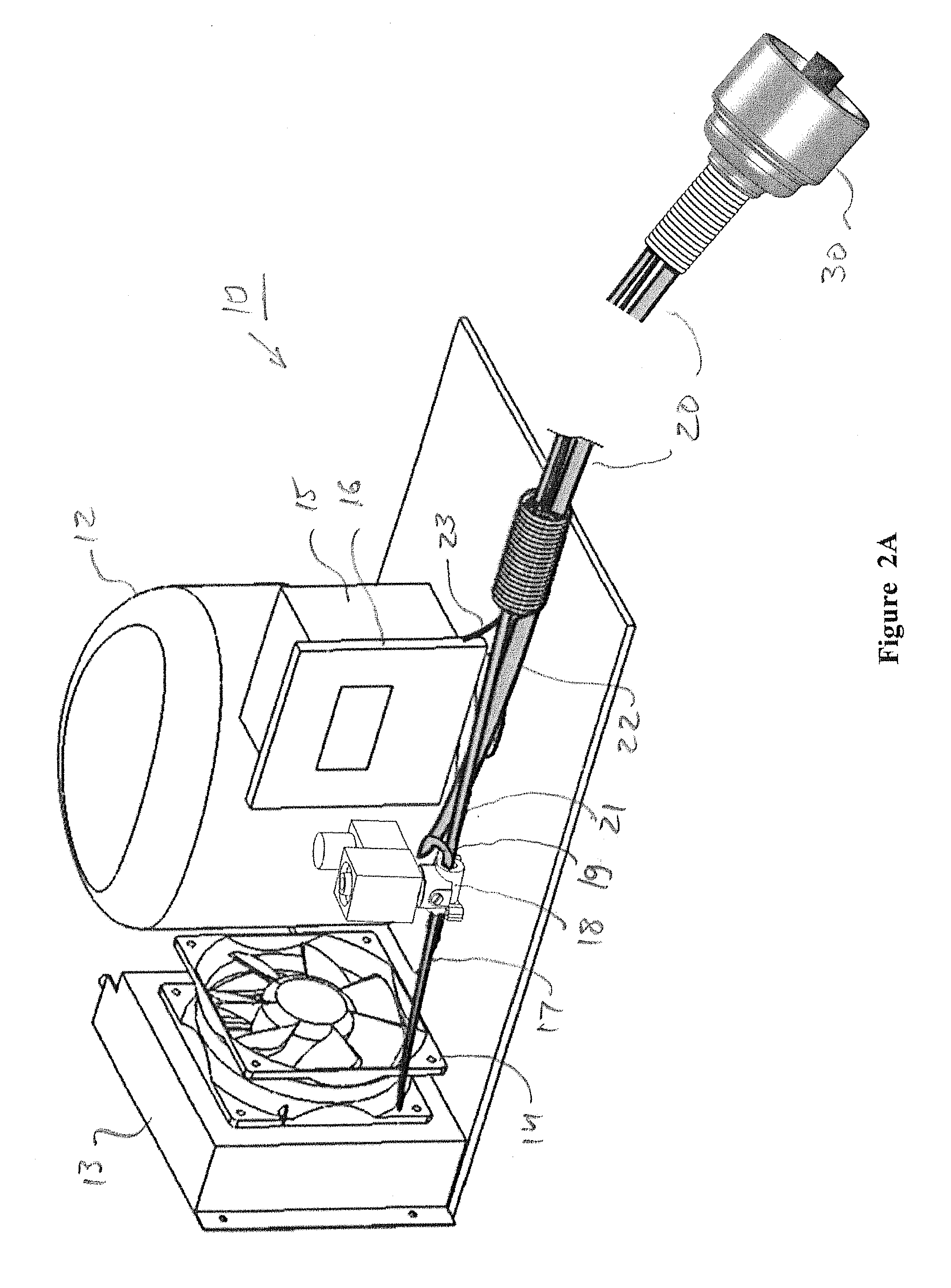
[0044]Reference is made to both FIG. 1, which shows a temperature-forcing system according to the invention schematically in block diagram manner, and FIG. 2A, which depicts in an isometric view, a particular embodiment of the system. The system is generally configured and operative to circulate a bi-phase refrigerant through a temperature-forcing head (thermal head).

[0045]A central unit 10, usually with an enclosing case (not shown), has a compressor 12, a condenser 13, in intimate thermal contact with and an atmospheric heat exchanger and an expansion valve 18. A pipe (not shown) connects the outlet of compressor 12 with the inlet of condenser 13 and another pipe 17 connects the outlet of condenser 13 to the inlet of expansion valve 18. The heat exchanger is in thermal communication with the atmosphere, aided by a fan 14. Also within the central unit 10 is a controller 15, in electrical communication with a control panel 16.

[0046]A tube assembly 20, preferably flexible, connects c...


PUM


Abstract

A temperature-forcing system, for controlling the temperature of an electronic device under test, comprisinga temperature-forcing head, including a face configured to be put in thermal contact with the device and an evaporator, in direct or indirect thermal contact with the face; anda refrigerant circulation subsystem, including a compressor, a condenser and a metering device;wherein the subsystem is configured to circulate a bi-phase refrigerant, in closed loop fashion, through the evaporator so that, during circulation, the refrigerant is maintained at high pressure between the compressor and the metering device and at low pressure while flowing through the evaporator.More specifically, in the disclosed system the refrigerant, while flowing through the evaporator at a low pressure, is operative to dissipate heat therefrom by evaporation and the evaporator or any part thereof is formed as a heat exchanger.

Description

FIELD OF THE INVENTION[0001]The present invention relates to temperature forcing of electronic components and, in particular, to temperature forcing of semiconductor chips and modules during testing.BACKGROUND OF THE INVENTION[0002]In the electronic components semiconductor industry it is generally required to subject prototypes and production samples of semiconductor devices (chips or modules) to thorough electrical testing. Since specifications of a device typically include the range of ambient temperatures over which it should be operable, each device under test (DUT), and more specifically its casing, must generally be held during part of such testing at each of the extreme temperature values of the specified range (thus simulating the required extreme ambient temperature values). Such extreme values are typically between 125 and 165 degrees centigrade, at the high end, and between −40 and −70 degrees centigrade, at the low end. The process of thus keeping the case temperature o...

Claims


Application Information

Patent Timeline
29 Aug 2013
Publication
US20130220579A1
IPC
F25B1/00; F25B39/02; F28D15/00; F25B21/02
CPC
F25B1/00; F25B21/02; F28D2021/0071; F28F3/12; F25B39/02; F25D19/006; G01R31/2874
Inventors
YOSEF, LIOR; SIMHON, EYAL