Efficient temperature forcing of semiconductor devices under test

a technology of temperature forcing and semiconductor devices, applied in refrigeration devices, compression machines with non-reversible cycles, lighting and heating apparatus, etc., can solve the problems of reducing process efficiency, insufficient to raise the casing temperature, and exothermic process of dut, so as to improve the temperature forcing process and reduce the device temperature. , the effect of increasing the thermal efficiency

Active Publication Date: 2013-12-26
SIMHON EYAL +2
View PDF8 Cites 11 Cited by
  • Summary
  • Abstract
  • Description
  • Claims
  • Application Information

AI Technical Summary

Benefits of technology

[0011]The present invention improves the process of temperature forcing of an electronic device under test, over prior art, by providing that the cooling of the device, or of a member in direct or indirect thermal contact therewith, be effected directly by the evaporation of a bi-phase refrigerant, rather than by the flow of an intermediate single-phase transfer fluid (gaseous or liquid) that, in turn, exchanges heat with a remote cooling apparatus. One important advantage of this arrangement, over prior art, is that it involves fewer stages of heat transfer, with their associated temperature differentials, thus achieving greater thermal efficiency—enabling, for example, to achieve lower device temperatures for a given set of refrigeration parameters or, conversely, to utilize a smaller and less powerful, compressor to attain a given device temperature. Another important advantage of this arrangement, to be explained below, is the greater speed at which the device temperature may be switched.

Problems solved by technology

When testing at a high extreme temperature, however, the exothermic process of the DUT may at times be insufficient to raise its casing temperature to the desired level, as all of the generated heat is dissipated by the ambient air and external devices.
Such a prior-art system has three major drawbacks: (a) The presence of two heat exchangers in tandem causes a relatively large cumulative temperature differential between the chiller and the DUT, thus reducing the efficiency of the process and placing a sometimes unacceptable limit on how low the temperature of the latter may be forced with a simple (single-stage) refrigeration system.
(c) The relatively large heat capacity of the circulating transfer fluid further limits the rate at which the temperature may be switched.

Method used


Image

  • Efficient temperature forcing of semiconductor devices under test
  • Efficient temperature forcing of semiconductor devices under test
  • Efficient temperature forcing of semiconductor devices under test

Examples


example 1

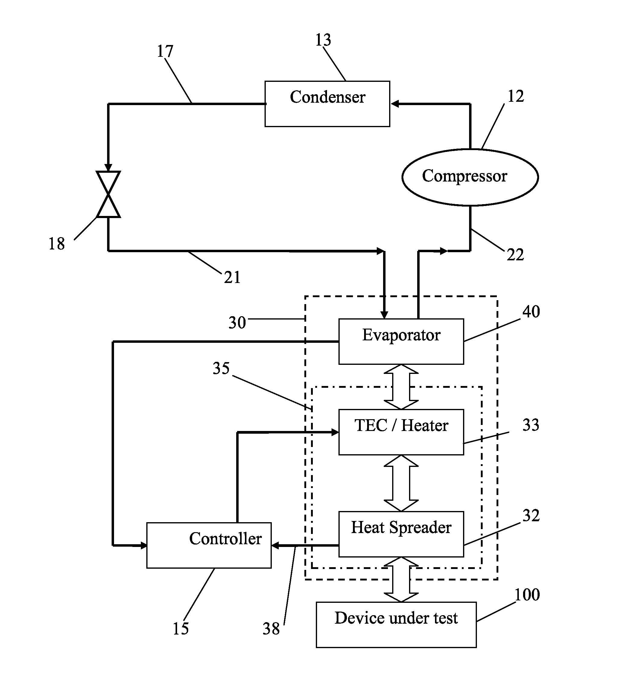
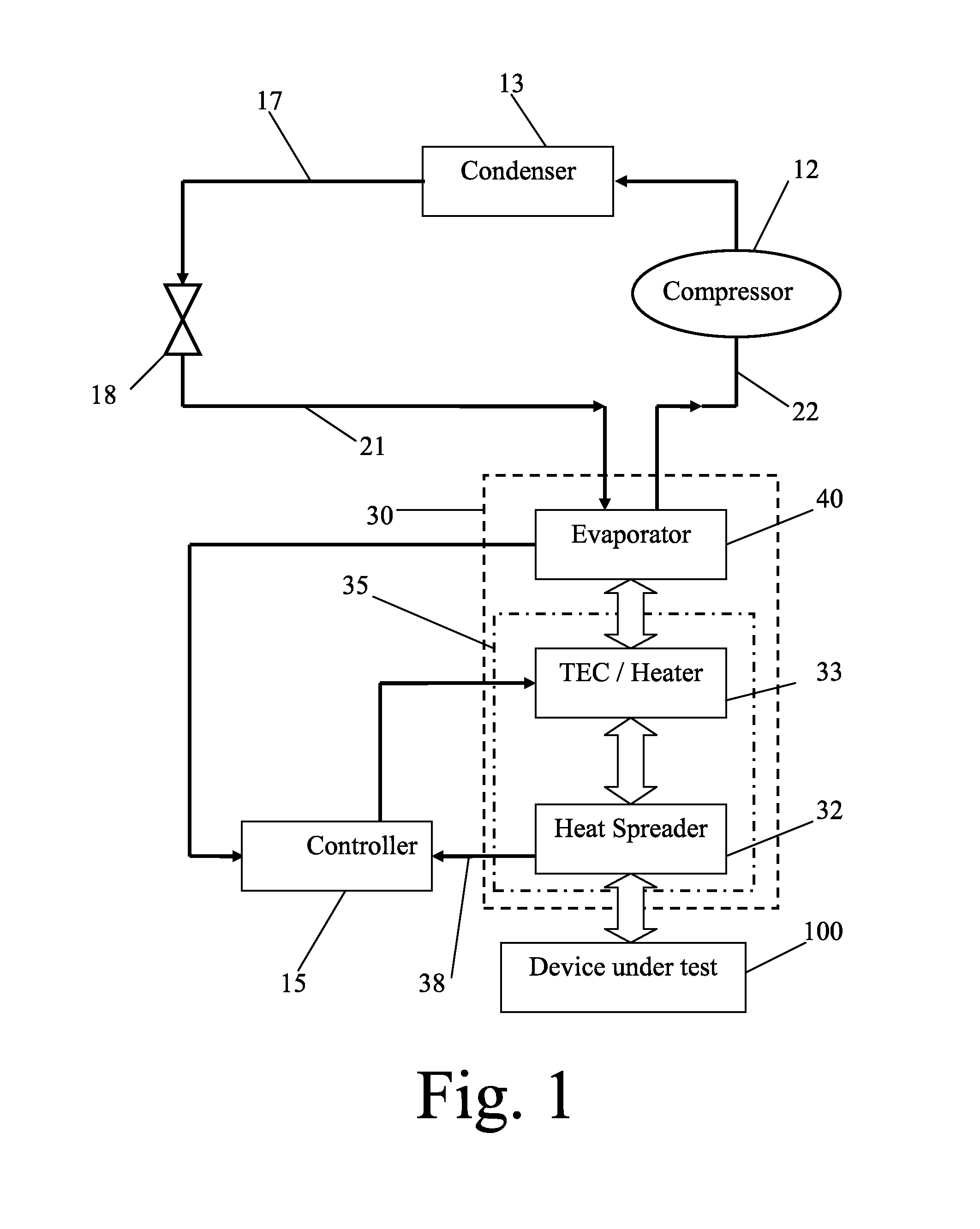
[0077]A field-programmable gate array (FPGA) device was subjected to temperature forcing at extreme temperatures ranging at an extreme high temperature between 135 and 200° C. and at an extreme low temperature between 0 and −60° C. Freon R404A was used as the refrigerant.

[0078]The compressor pressurized the refrigerant to a pressure of 250-300 psi, resulting in a temperature of 50° C., and provided a suction pressure of 10-20 psi. The refrigerant was cooled by an air-cooled type condenser to a temperature of 30° C. A capillary tube lowered the pressure of the refrigerant to 20 psi and its temperature to −30° C.

[0079]The cooled refrigerant was delivered to a labyrinth type evaporator retained in the temperature-forcing head, and was evaporated as a result of heat transfer from the FPGA device, producing a temperature of −55° C. at a heat dissipation rate of up to 1 kW.

[0080]The compressor operated continuously during the cooling phase, and was not operated during the heating phase. A...

example 2

[0082]A FPGA device was subjected to temperature forcing at extreme temperatures ranging at an extreme high temperature between 135 and 200° C. and at an extreme low temperature between −30 and −70° C. Freon R23 was used as the refrigerant in thermal contact with the device. The temperature-forcing head was not provided with a thermoelectric cooler, but rather the low temperatures were made possible by a two stage refrigeration cycle and the high temperatures were achieved by the use of a resistive heater.

[0083]In the first stage, a first compressor pressurized the R404A refrigerant to a pressure of 250-300 psi, resulting in a temperature of 50° C., and provided a suction pressure of 10-20 psi. The refrigerant was cooled by an air-cooled type condenser to a temperature of 30° C. A capillary tube lowered the pressure of the refrigerant to 20 psi and its temperature to −30° C.

[0084]In the second stage, a second compressor pressurized the R23 refrigerant to a pressure of 400-600 psi, r...


PUM


Abstract

A temperature-forcing system and method for controlling the temperature of an electronic device under test comprises a temperature-forcing head, including a face positionable in thermal contact with the device, and an evaporator, in direct or indirect thermal contact with the face; and a refrigerant circulation subsystem, including a compressor, a condenser, a flow control device for inducing a pressure drop in the refrigerant, and a conduit circuit through which the refrigerant is flowable. The subsystem cooperates with the evaporator so as to define at least one closed loop through which a corresponding bi-phase refrigerant is circulatable, so that, during circulation, the refrigerant is maintained in a liquid phase between the compressor and the flow control device and in a gaseous phase while flowing through the evaporator. The temperature of the device is therefore switchable by the head at a rapid rate of 50 to 150 degrees Celsius per minute.

Description

[0001]The present application is a continuation-in-part of U.S. application Ser. No. 13 / 405,870 filed Feb. 27, 2012 and bearing the same title.FIELD OF THE INVENTION[0002]The present invention relates to temperature forcing of electronic components and, in particular, to temperature forcing of semiconductor chips and modules during testing.BACKGROUND OF THE INVENTION[0003]In the electronic components semiconductor industry it is generally required to subject prototypes and production samples of semiconductor devices (chips or modules) to thorough electrical testing. Since specifications of a device typically include the range of ambient temperatures over which it should be operable, each device under test (DUT), and more specifically its casing, must generally be held during part of such testing at each of the extreme temperature values of the specified range (thus simulating the required extreme ambient temperature values). Such extreme values are typically between 125 and 165 degr...

Claims


Application Information

Patent Timeline
Patent Type & Authority Applications(United States)
IPC IPC(8): H05K7/20
CPCH05K7/20F25B21/02F28F3/12F28D2021/0071F25B1/10F25D19/006G01R31/2874
Inventor YOSEF, LIORSIMHON, EYAL
Owner SIMHON EYAL
Why Eureka
Try Eureka