Ion-mode plasma containment

a plasma containment and plasma technology, applied in nuclear reactors, nuclear engineering, greenhouse gas reduction, etc., can solve the problems of difficult economic containment of plasma, and achieve the effect of reducing the conductivity of electrons and increasing the poloidal magnetic field

Active Publication Date: 2013-08-29
UTAH STATE UNIVERSITY
View PDF1 Cites 5 Cited by
  • Summary
  • Abstract
  • Description
  • Claims
  • Application Information

AI Technical Summary

Problems solved by technology

Unfortunately, plasma has been difficult to contain economically.

Method used


Image

  • Ion-mode plasma containment
  • Ion-mode plasma containment
  • Ion-mode plasma containment

Examples


Embodiment Construction

[0032]Reference throughout this specification to “one embodiment,”“an embodiment,” or similar language means that a particular feature, structure, or characteristic described in connection with the embodiment is included in at least one embodiment. Thus, appearances of the phrases “in one embodiment,”“in an embodiment,” and similar language throughout this specification may, but do not necessarily, all refer to the same embodiment, but mean “one or more but not all embodiments” unless expressly specified otherwise. The terms “including,”“comprising,”“having,” and variations thereof mean “including but not limited to,” unless expressly specified otherwise. An enumerated listing of items does not imply that any or all of the items are mutually exclusive, unless expressly specified otherwise. The terms “a,”“an,” and “the” also refer to “one or more” unless expressly specified otherwise.

[0033]Furthermore, the described features, structures, or characteristics of the embodiments may be c...


PUM


Abstract

For ion-mode plasma containment, a toroidal vacuum vessel (322) has a major radius (208) and a minor radius (212). The toroidal vacuum vessel (322) is filled with a gas (391) having an initial particle density. An ionizing device (341) ionizes the gas (391) into a plasma (400). A transformer inductively (326) drives a toroidal particle current (332) comprising an ion current and an electron current about a toroidal axis. The toroidal particle current (322) heats the plasma (400) and generates a poloidal magnetic field (373). Field coils (414) wound poloidally about the toroidal vacuum vessel (322) generate a toroidal magnetic field (371). The toroidal magnetic field (371) at a wall of the toroidal vacuum vessel (322) is adjusted to satisfy a boundary condition for a minimum-energy. The plasma (400) is contained by the radial electric field, the poloidal magnetic field (373), and the toroidal magnetic field (371) within the toroidal vacuum vessel (322) in the minimum-energy state.

Description

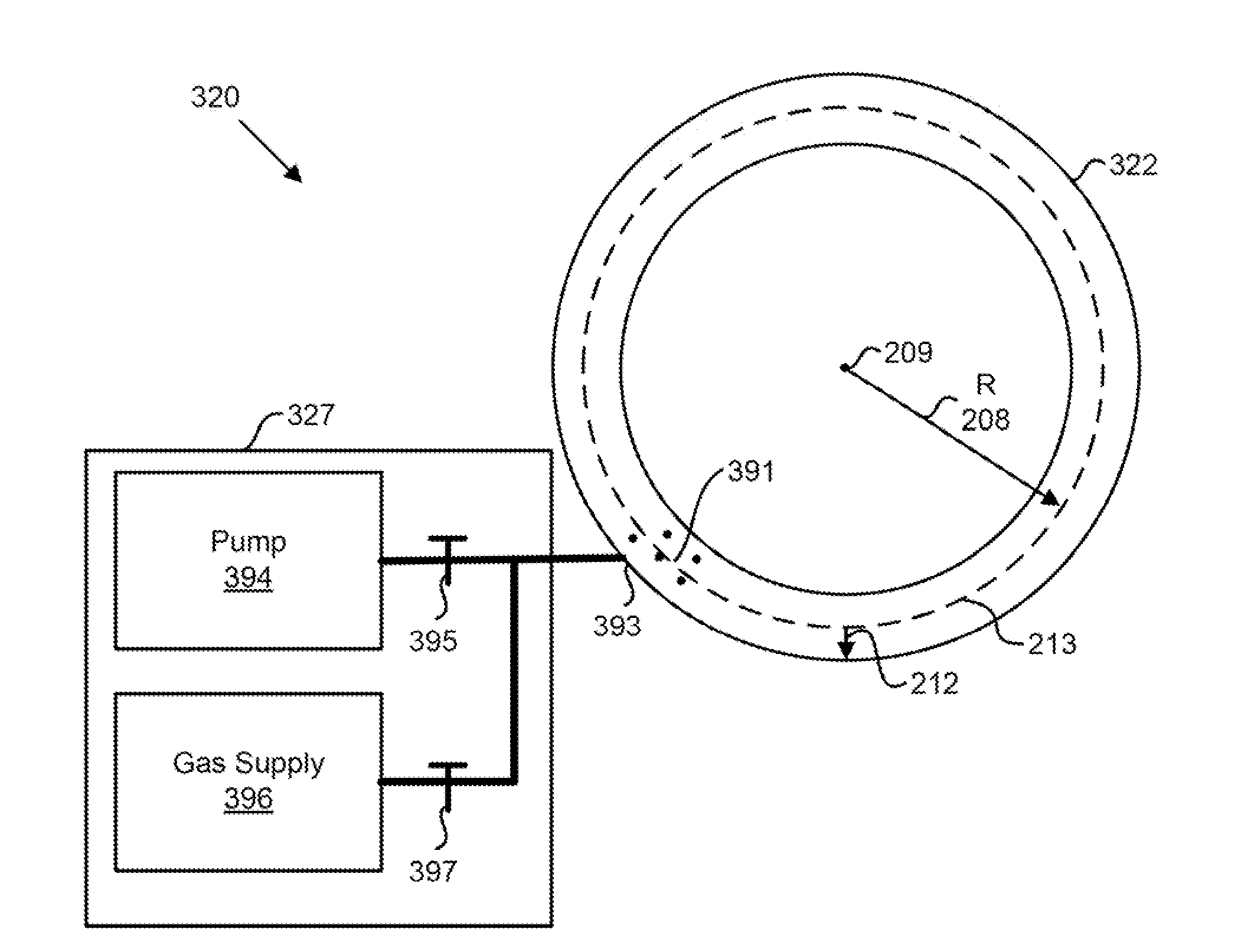
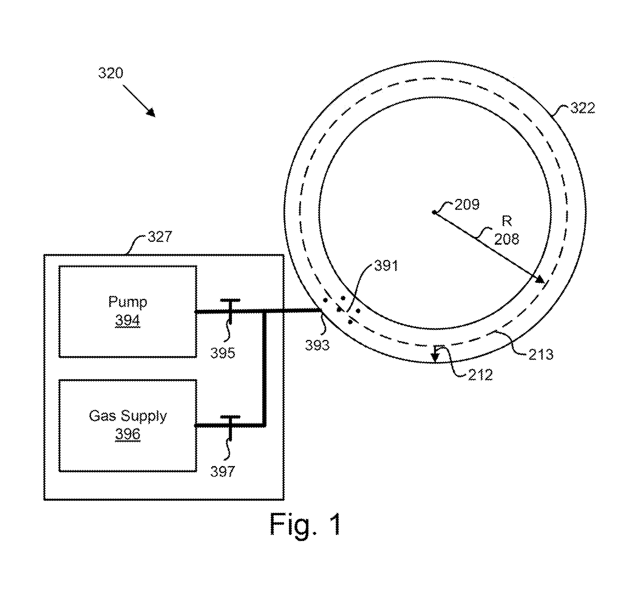
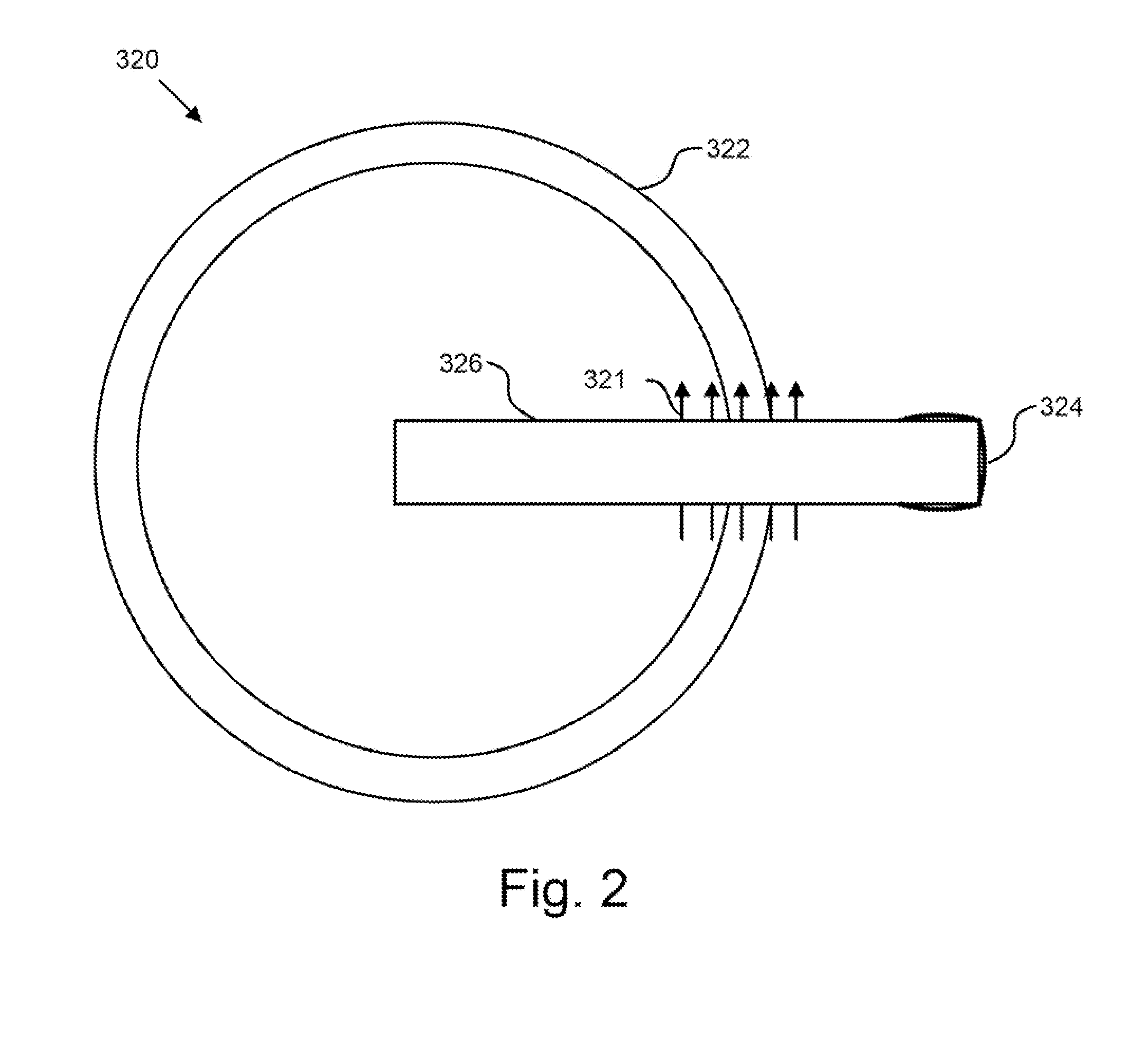
CROSS-REFERENCE TO RELATED APPLICATION[0001]This application claims priority to U.S. Provisional Patent Application No. 61410978 entitled “ION-MODE PLASMA CONTAINMENT” and filed on Nov. 8, 2010 for W. Farrell Edwards et al., which is incorporated herein by reference.FIELD[0002]The subject matter disclosed herein relates to plasma containment and more particularly relates to ion-mode plasma containment.BACKGROUNDDESCRIPTION OF THE RELATED ART[0003]Plasma has a number of important applications. Unfortunately, plasma has been difficult to contain economically.BRIEF SUMMARY[0004]An apparatus is disclosed for plasma containment. A toroidal vacuum vessel has a major radius R and a minor radius α. The toroidal vacuum vessel is filled with a as having, an initial particle density n, where n=(mη2) / (a2μoe2), m is a mass of an ion charge carrier, μ0 is the permeability of free space, e is the electron charge, and η is a constant in the range of 1 to 2. An ionizing device ionizes the gas into a...

Claims


Application Information

Patent Timeline
Patent Type & Authority Applications(United States)
IPC IPC(8): H05H1/18
CPCG21B1/05H05H1/12Y02E30/126H05H1/18Y02E30/122Y02E30/10
Inventor EDWARDS, W. FARRELLHELD, ERIC D.SINGH, AJAY K.
Owner UTAH STATE UNIVERSITY
Why Eureka
Try Eureka