Distributed Optical Fibre Sensor

a technology of optical fibre and optical fiber filter, applied in the direction of testing fibre optic/optical waveguide devices, fluid pressure measurement, instruments, etc., can solve problems such as troublesome limitation, and achieve low weighting, low noise, and high level

Active Publication Date: 2013-08-29
VIAVI SOLUTIONS INC
View PDF12 Cites 52 Cited by
  • Summary
  • Abstract
  • Description
  • Claims
  • Application Information

AI Technical Summary

Benefits of technology

[0033]FIG. 3 illustrates a method for enhancing the detection rate of the sensor of FIG. 1 using interleaving;
[0036]FIG. 6 illustrates use of an ensemble of pulse lengths to increase sensor dynamic range;

Problems solved by technology

For very long sensing fibres, this limitation can become troublesome.

Method used


Image

  • Distributed Optical Fibre Sensor
  • Distributed Optical Fibre Sensor
  • Distributed Optical Fibre Sensor

Examples


Embodiment Construction

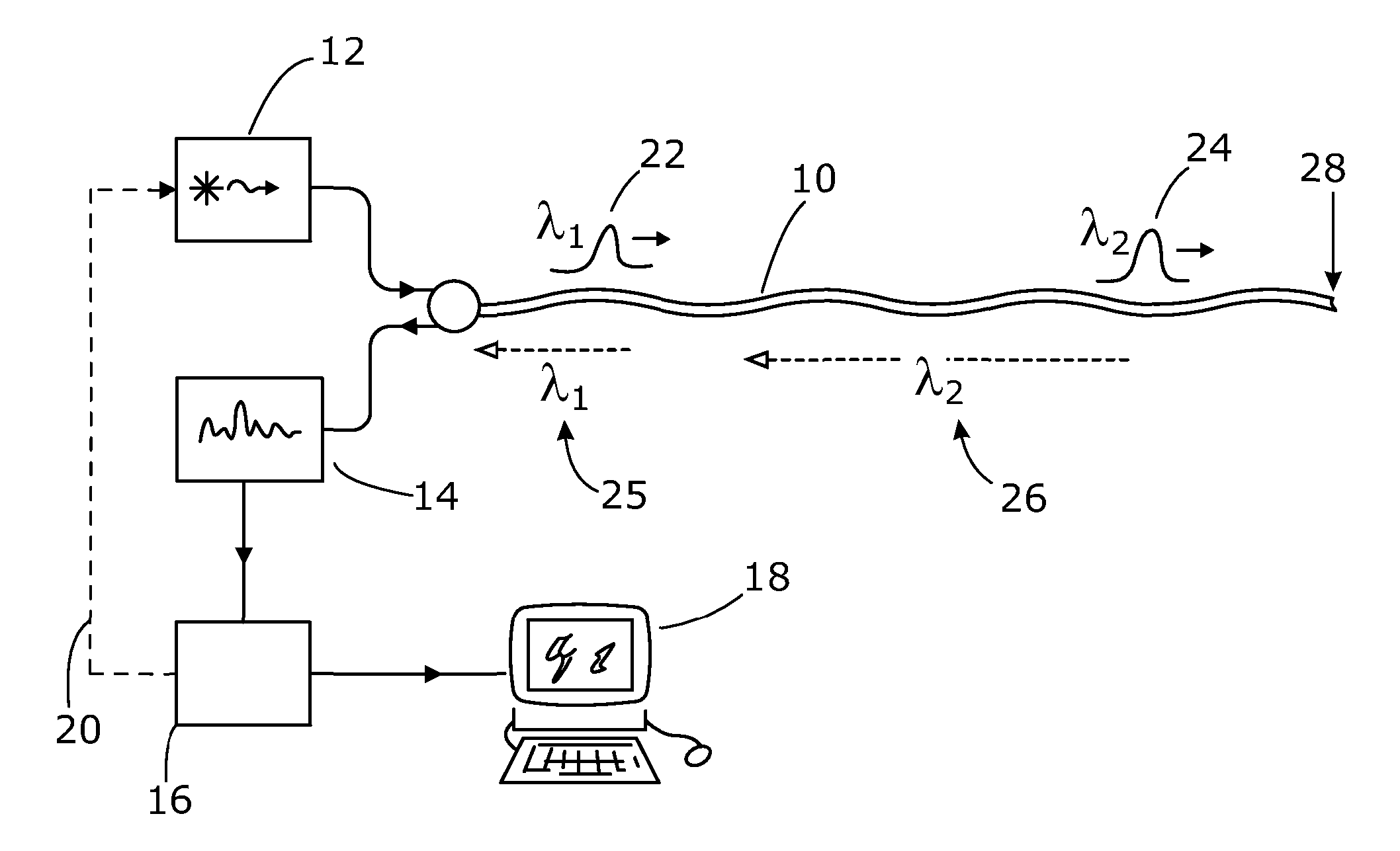
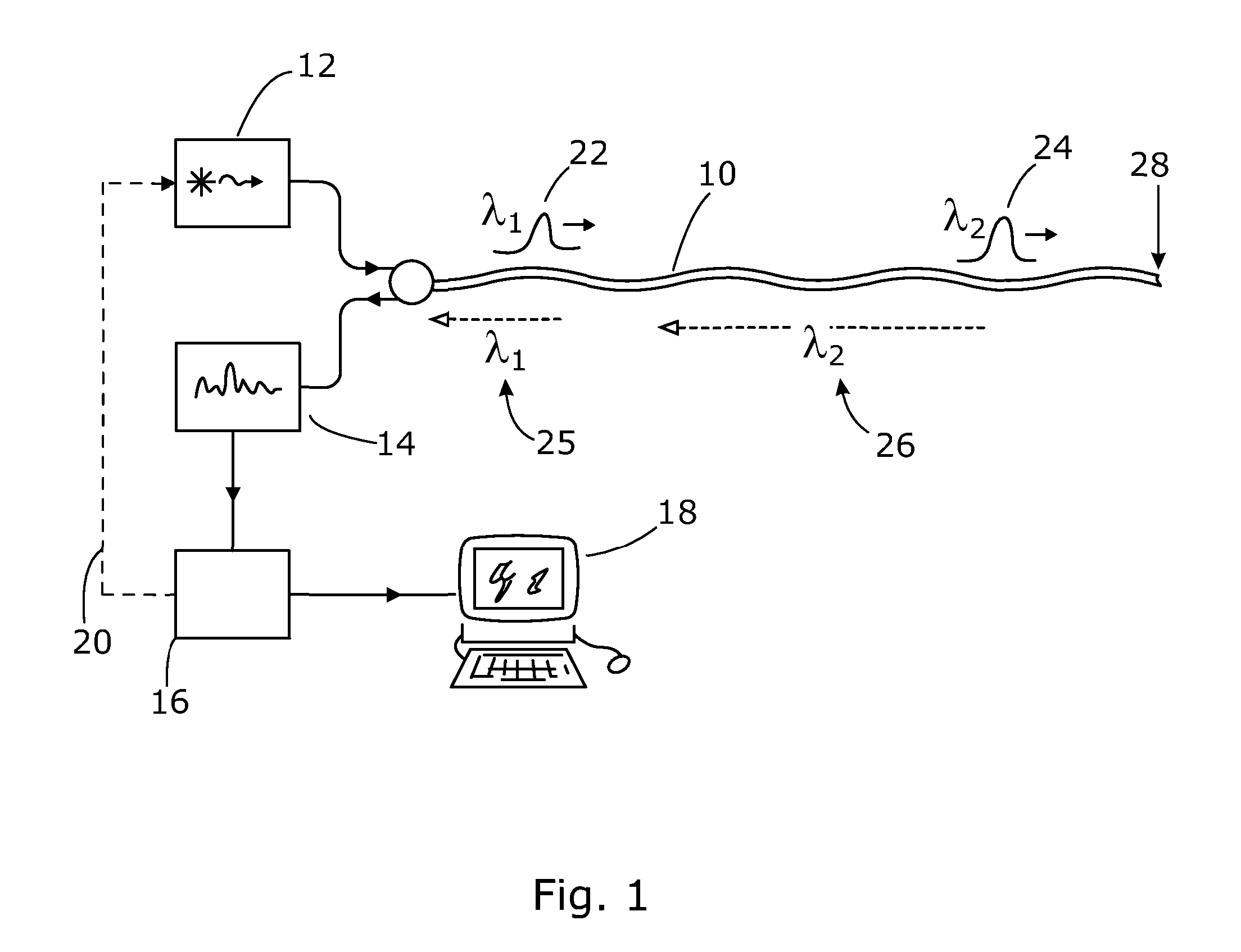
[0041]Referring to FIG. 1 there is illustrated a distributed optical fibre sensor suitable for sensing one or more physical parameters as a function of position along part or all of the sensing optical fibre 10, using time domain reflectometry. The sensor includes the sensing fibre 10, a probe light source 12 for launching probe light pulses into the sensing fibre, a detector 14 for detecting probe light which has been backscattered within the sensing fibre 10, and an analyser 16 for processing data received from the detector.

[0042]The analyser 16 outputs analysis results such as a determination of the one or more physical parameters, and in FIG. 1 this output is passed to a computer display 18, although various other types of output mechanism may be used. The analyser 16 also uses data derived from the detected backscatter to provide control signals 20 to the probe light source 12. A variety of control signals may be provided, some of which are discussed below, including signals co...


PUM


Abstract

There is described a distributed optical fibre sensor for detecting one or more physical parameters indicative of an environmental influence on a sensor optical fibre, as a function of position along the sensor fibre. The sensor uses probe light pulses of different wavelengths. At least some of the probe light pulses may also be of different pulse lengths. The relative phase bias between interferometric signals in backscattered probe light of different wavelength pulses may also be controlled.

Description

[0001]The present invention relates to distributed optical fibre sensors, in which one or more physical parameters are sensed as a function of position along a sensing optical fibre from the properties of probe light backscattered within the sensing fibre. In particular, but not exclusively, the invention relates to optical time domain reflectometry (OTDR) sensors for use in sensing vibration, and such sensors which use phase sensitive OTDR techniques such as through the detection of coherent Rayleigh noise, or other interferometric techniques.INTRODUCTION[0002]Distributed optical fibre sensing is a well known approach to providing information about environmental conditions surrounding a sensing optical fibre. Fully-distributed sensing in principle provides spatially resolved information from every point along the fibre. Variables that can be sensed include temperature, static strain, pressure, and vibration.[0003]One such technique detects variations in refractive index, induced by...

Claims


Application Information

Patent Timeline
Patent Type & Authority Applications(United States)
IPC IPC(8): G01D5/353
CPCG01M11/3127G01D5/35306G01D5/35358G01D5/35303G01L11/025G01H9/004G01M11/3145
Inventor HANDEREK, VINCENT
Owner VIAVI SOLUTIONS INC
Why Eureka
Try Eureka