Magnetic resonance imaging system, computer system, and computer program product for sending control messages to an anesthesia system

Inactive Publication Date: 2013-08-29
KONINKLIJKE PHILIPS ELECTRONICS NV
View PDF4 Cites 17 Cited by
  • Summary
  • Abstract
  • Description
  • Claims
  • Application Information

AI Technical Summary

Benefits of technology

[0032]In another embodiment each tissue oxygenation level measure is calculated during the acquisition of magnetic resonance data. The instructions further cause the processor to perform the step of modifying the pulse sequence and / or the gas sequence in accordance with the set of tissue oxygen level measures. The gas sequence could be modified by measuring the effect of the tissue oxygen level measures. For instance, if a sufficient change in the tissue oxygen level is detected then the experiment could be terminated and the gas sequence could be modified such that the subject is breathing normal air. Depending on the contrast of the set of tissue oxygen level measures detected in magnetic resonance images the pulse sequence can be modified. For instance the repetition time and the number of echoes used for the T2* measurement may be modified.

Problems solved by technology

A difficulty with current Respiratory Challenge (RC) procedures is that the conventional regime comprises one or more MR scans, executed while the patient is inhaling changing compositions of O2, CO2 or inhalation of other inhalation gases, also known as a RC, units that are controlled completely separately and independently from the MR unit.
Problems arise, when the MR scan had not been perfectly synchronized to the RC protocol or vice versa, e.g. due to:misunderstandings of technicians and radiologists outside the MR room with the anesthetist inside the MR room,timing uncertainties,leakage of the inhalation mask, via which the patient inhales the applied mixtures, orpost-processing fails, when the (manual) RC protocol recording gets lost or is incorrect.

Method used


Image

  • Magnetic resonance imaging system, computer system, and computer program product for sending control messages to an anesthesia system
  • Magnetic resonance imaging system, computer system, and computer program product for sending control messages to an anesthesia system
  • Magnetic resonance imaging system, computer system, and computer program product for sending control messages to an anesthesia system

Examples


Embodiment Construction

[0050]Like numbered elements in these figures are either equivalent elements or perform the same function. Elements which have been discussed previously will not necessarily be discussed in later figures if the function is equivalent.

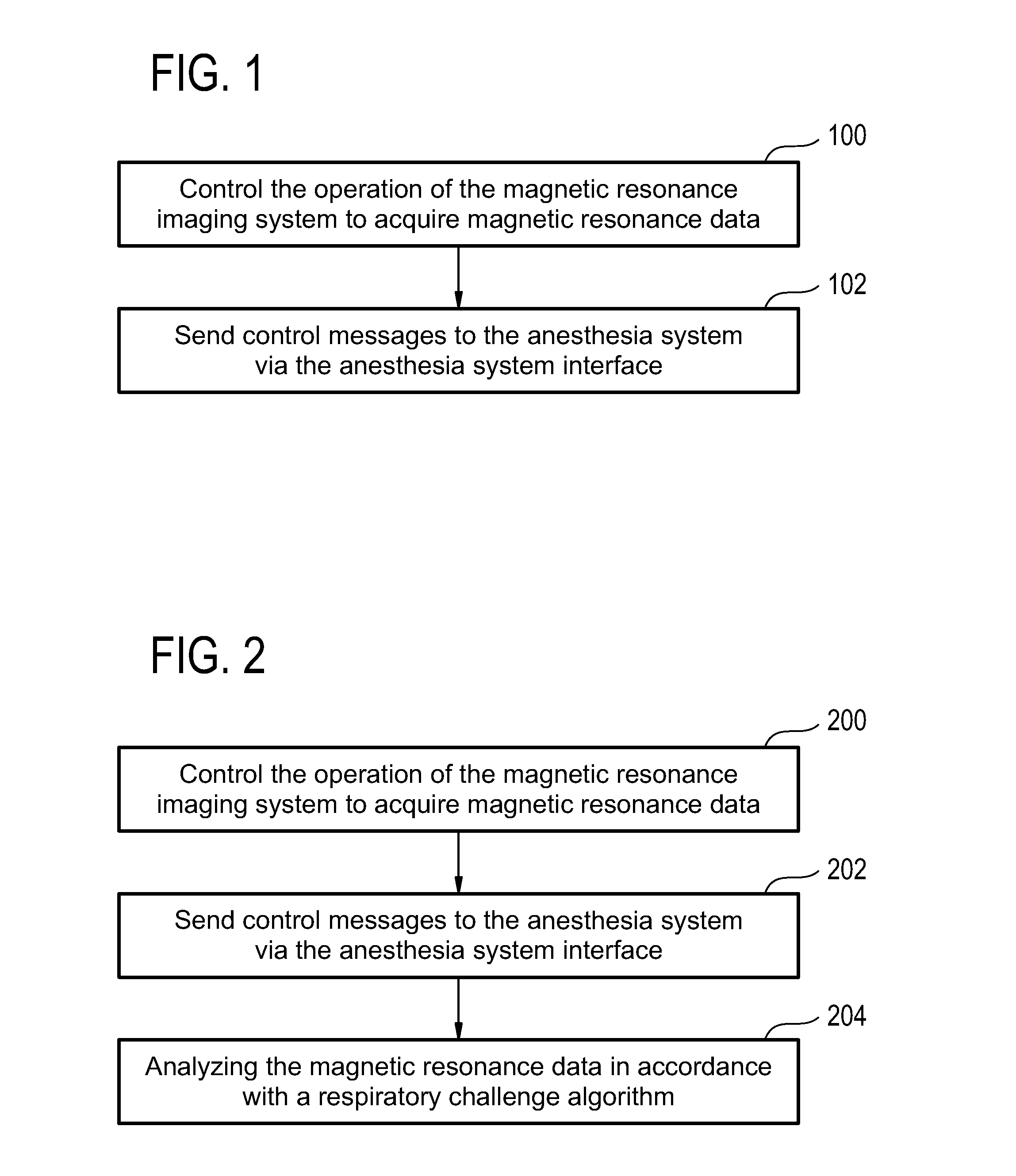
[0051]FIG. 1 shows a block diagram which illustrates an embodiment of a method according to the invention. In step 100 the operation of the magnetic resonance imaging system is controlled to acquire magnetic resonance data. In step 102 control messages are sent to the anesthesia system via the anesthesia system interface.

[0052]FIG. 2 shows a block diagram which illustrates an embodiment of a further method according to the invention. In step 200 the operation of the magnetic resonance imaging system is controlled in order to acquire magnetic resonance data. In step 202 control messages are sent to the anesthesia system via the anesthesia system interface. In step 204 the magnetic resonance data is analyzed in accordance with a respiratory challenge algo...


PUM


Abstract

A magnetic resonance imaging system (500) comprising: a magnet (502) for generating a magnetic field; a radio frequency system (516) for acquiring magnetic resonance data; a magnetic field gradient coil (510) for spatial encoding of the magnetic spins of nuclei within the imaging volume; a magnetic field gradient coil power supply (512) for supplying current to the magnetic field gradient coil; an anesthesia system interface (532) for sending control messages to an anesthesia system (524) for controlling the delivery of inhalation gases to a subject and a computer system comprising a processor (534) and a memory (538, 540), wherein the memory contains instructions (542, 544, 546, 548, 550, 552) for execution by the processor, wherein execution of the instructions causes the processor to: control (100, 200, 300, 400) the operation of the magnetic resonance imaging system to acquire magnetic resonance data, and to send (102, 202, 302, 402) control messages to the anesthesia system via the anesthesia system interface.

Description

TECHNICAL FIELD [0001]The invention relates to magnetic resonance imaging, in particular to the simultaneous control of a magnetic resonance imaging system and an anesthesia systemBACKGROUND OF THE INVENTION [0002]Measuring the Magnetic Resonance (MR) response to Respiratory Challenges (RC) that induce elevated levels of O2 (hyperoxia) and CO2 (hypercapnia) gives insight into a wide range of physiologic parameters like blood and tissue oxygenation, vessel maturation and function, tumor hypoxia and cerebrovascular reactivity. These parameters play a major role in oncologic research e.g. in tumor therapy selection, planning (dosage) and monitoring. In those experiments, the patient inhales O2 and / or CO2-enriched air, which results in a modulation of blood flow, volume and oxygenation depending on the maturity and oxygen function of vessels and / or the amount of dissolved oxygen in blood plasma and tissue. In response, MR relaxation rates and thus the MR contrast changes, according to t...

Claims


Application Information

Patent Timeline
Patent Type & Authority Applications(United States)
IPC IPC(8): G01R33/56A61B5/055
CPCG01R33/5608A61B5/055A61M16/01A61M16/104A61M2016/102A61M2016/1025A61M2016/103A61M2205/057A61M2230/005A61M2230/43A61M2230/432A61M2230/435G01R33/30G01R33/5601G01R33/56366A61M16/024
Inventor REMMELE, STEFANIESTEHNING, CHRISTIAN
Owner KONINKLIJKE PHILIPS ELECTRONICS NV
Why Eureka
Try Eureka