
Two Engine System With A Gaseous Fuel Stored In Liquefied Form

Active Publication Date: 2013-09-05
WESTPORT FUEL SYST CANADA INC
View PDF5 Cites 22 Cited by
  • Summary
  • Abstract
  • Description
  • Claims
  • Application Information

AI Technical Summary

Benefits of technology

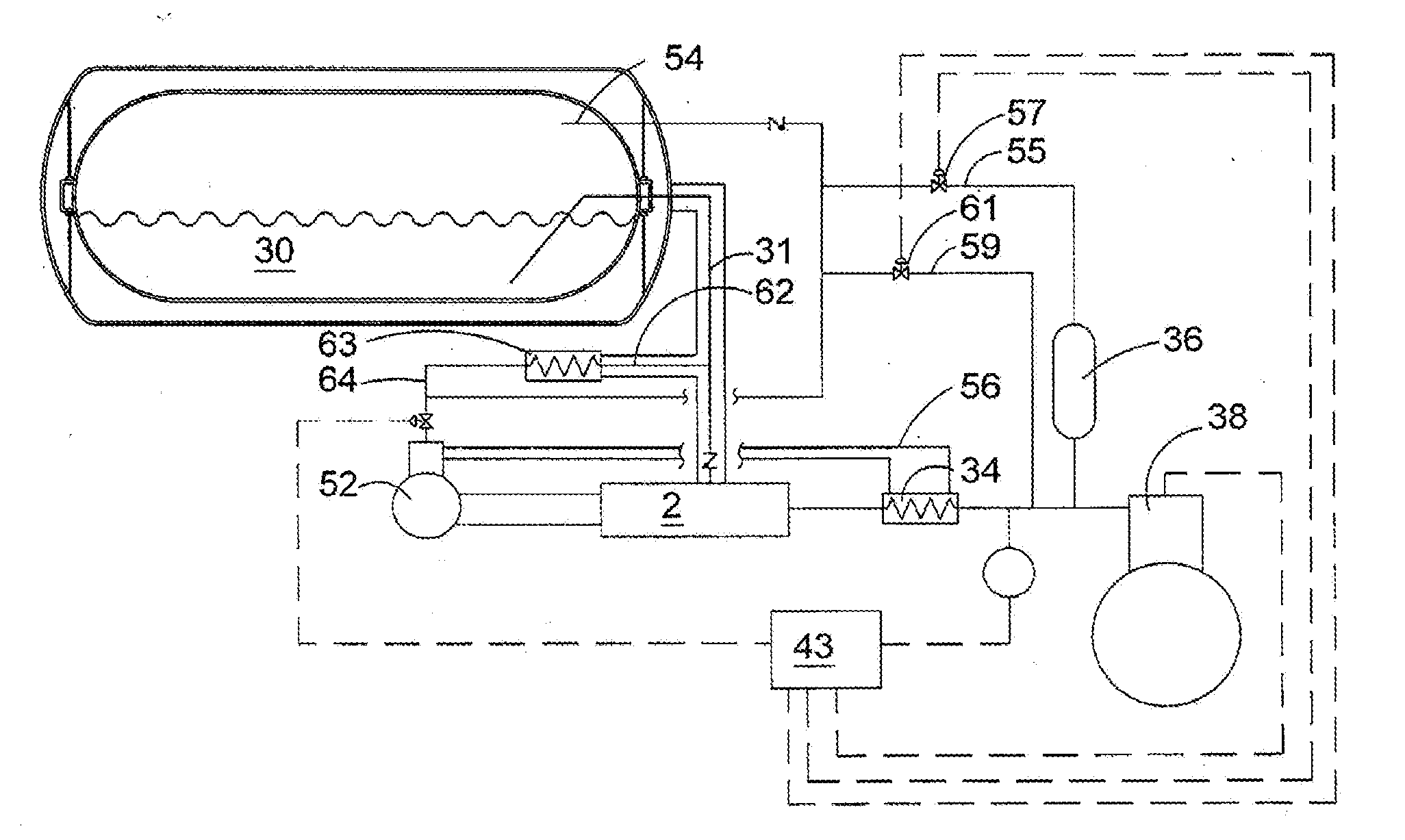
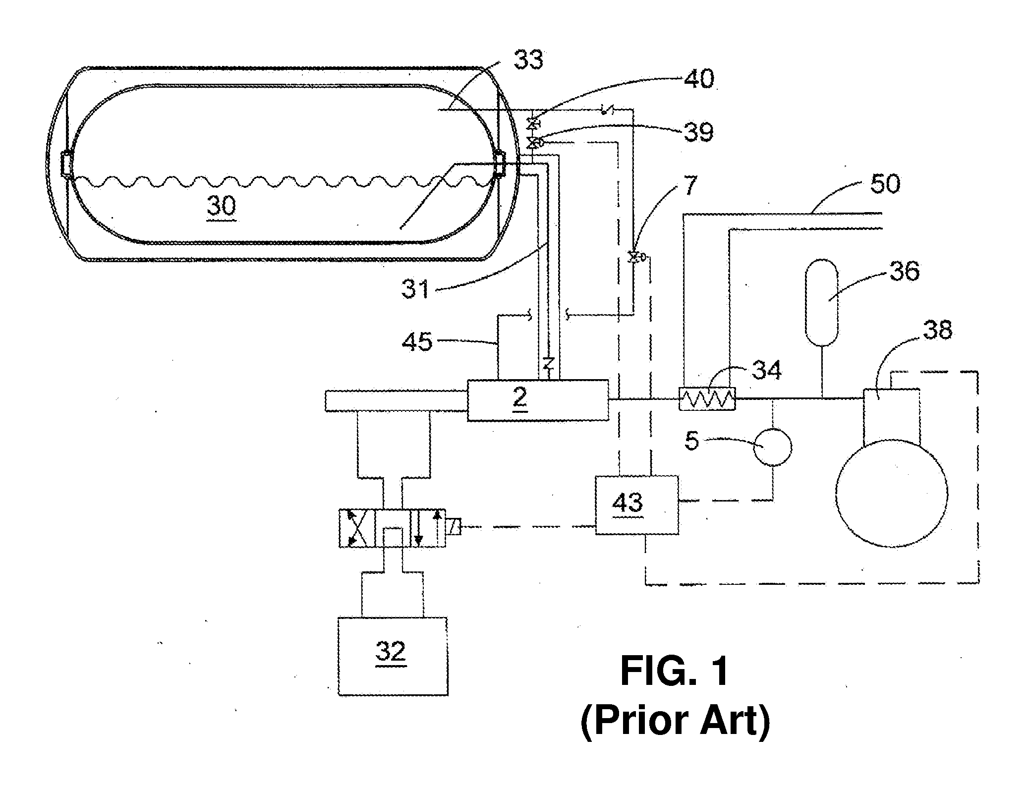
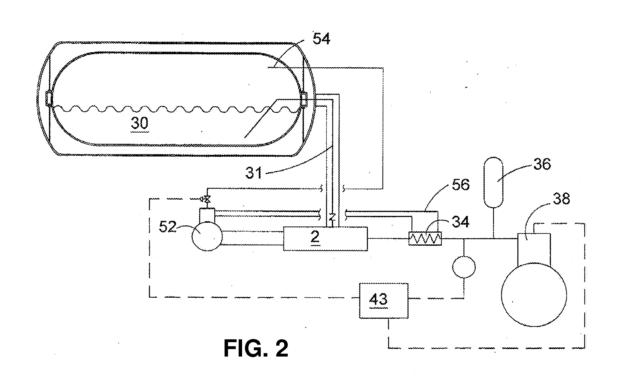
The patent text discusses a system for vehicles that use a gaseous fuel, such as natural gas, and a separate auxiliary engine for use in fuel supply and other applications. The auxiliary engine is smaller and less efficient than the main engine, but it can still provide useful power without wasting any of the unused fuel. By using the auxiliary engine, the overall efficiency of the system can still be high, and it simplifies the fuel supply system and improves reliability. The system also includes an accumulator to reduce pressure fluctuations in the fuel. The cryogenic pump in the system can be a reciprocating piston pump, and the fumigated engine can directly drive it, eliminating the need for additional hydraulic lines and reservoirs. The speed of the fumigated engine can also be controlled according to demand.

Problems solved by technology

While natural gas has been used as a fuel for vehicles for over fifty years, widespread use has been curtailed for various reasons including fuel storage density, infrastructure, availability of fuel, and capital costs that are generally higher compared to conventional liquid-fuelled vehicles.
CNG is commonly stored at ambient temperatures at pressures up to 250 bar, but a disadvantage of CNG is its lower energy density compared to conventional liquid fuels or LNG and the relatively heavy weight normally associated with CNG storage tanks, which need to be designed to withstand the high storage pressures.
However, using LNG as a fuel supply introduces some complications in the fuel handling and supply systems.
One complication is that the liquefied natural gas must be warmed and converted into gaseous form before being supplied to the engine.
However, because cryogenic storage tanks require structural elements and pipes for filling and dispensing the fuel, there is at least some amount of heat transfer into the storage space, and when heat is absorbed by the stored liquefied gas, some of it can be converted to vapor which has a lower density than the liquefied gas, causing an increase in the storage pressure.
Because of the high injection pressures needed for HPDI engines, such engines are unable to use the BOG vented from the storage tank because the BOG pressure is too low and it is not efficient and therefore not practical to compress the vapor to the high pressures needed for direct injection into the combustion chamber.
With some of these approaches there can still be times when a small amount of BOG cannot be directed to useful applications, resulting in the BOG being vented from the storage tank.
There is a need to prevent the venting of BOG because this represents waste, while also posing emissions and safety concerns.

Method used


Image

  • Two Engine System With A Gaseous Fuel Stored In Liquefied Form
  • Two Engine System With A Gaseous Fuel Stored In Liquefied Form
  • Two Engine System With A Gaseous Fuel Stored In Liquefied Form

Examples


example

[0038]The following illustrative example demonstrates a potential improvement in parasitic power as a result of using the disclosed system. However, this example should not be construed as limiting. Based on scaling up system performance of a reciprocating hydraulically actuated cryogenic pump, the projected parasitic power for a vehicle using a 4900 W engine is about 115 KW or 2.3%. However, based on the work done on the cryogenic fluid and typical efficiencies of mechanical drives, the projected parasitic power for the same vehicle employing an additional fumigated engine of similar efficiency in place of the hydraulic drive is about 0.8%. If the smaller auxiliary fumigated engine had a lower efficiency (in particular, 30% brake thermal efficiency compared to 40% for the main HPDI engine of the vehicle), the projected parasitic fuel flow would be 1.2% of the direct injection flow.


PUM


Abstract

A gaseous fuelled two-engine system comprises a high pressure direct injection engine as the main power source and an auxiliary fumigated engine that can be fuelled with vapor removed from a storage tank that stores the gaseous fuel in liquefied form at cryogenic temperatures. The fuel supply system comprises a cryogenic pump for raising the pressure of the fuel to the injection pressure needed for the high pressure direct injection engine, and the cryogenic pump is powered by the auxiliary fumigated engine.

Description

CROSS-REFERENCE TO RELATED APPLICATION(S)[0001]This application is a continuation of International Application No. PCT / CA2011 / 050518, having an international filing date of Aug. 25, 2011, entitled “Two Engine System With A Gaseous Fuel Stored In Liquefied Form”. The '518 international application claimed priority benefits, in turn, from Canadian Patent Application No. 2,716,283 filed Oct. 1, 2010, also entitled “Two Engine System With a Gaseous Fuel Stored in Liquefied Form”. The '518 international application is hereby incorporated by reference herein in its entirety.FIELD OF THE INVENTION [0002]The present invention relates to a two-engine system with a gaseous fuel stored in liquefied form. In one particular embodiment, the gaseous fuel is natural gas which is stored on board a vehicle in liquefied form at cryogenic temperatures. The present invention also relates to a method and apparatus for preventing the release of boil-off gas into the atmosphere.BACKGROUND OF THE INVENTION[...

Claims


Application Information

Patent Timeline
IPC IPC(8): F02B17/00
CPCF02M21/0209F17C2270/0173F02M21/06Y02T10/32F02M21/0245F02M21/0275F02D19/022F02D19/027F02B17/005F01B21/00F02B43/02F02B73/00F02B2043/103F17C2221/033F17C2223/0161F17C2223/033F17C2223/043F17C2223/047F17C2225/0123F17C2225/036F17C2227/0135F17C2227/0142F17C2227/0323F17C2227/0393F17C2250/01F17C2250/032F17C2250/043F17C2265/066F17C2270/0105F17C2270/0168F17C2270/0171F02M21/0221Y02T10/30
Inventor DUNN, MARK E.LEBLANC, VALERIE N.
Owner WESTPORT FUEL SYST CANADA INC
Learn More