Thermally-assisted magnetic recording head including a magnetic pole and a heating element

a magnetic recording head and heating element technology, applied in the field of thermo-assisted magnetic recording head, can solve the problems of increasing the coercivity of the magnetic recording medium, the loss of magnetic fine particles in the thermal stability of magnetization, and the difficulty of data writing with existing magnetic recording heads, so as to reduce the distance between the peak write magnetic field point and the peak heat poin

Active Publication Date: 2013-09-05
TDK CORPARATION
View PDF1 Cites 6 Cited by
  • Summary
  • Abstract
  • Description
  • Claims
  • Application Information

AI Technical Summary

Benefits of technology

[0022]It is an object of the present invention to provide a thermally-assisted magnetic recording head and a method of manufacturing the same, the thermally-assisted magnetic recording head being configured so that the peak write magnetic field point is located on the trailing side relative to the peak heat point and being capable of reducing the distance between the peak write magnetic field point and the peak heat point, and to provide a head gimbal assembly and a magnetic recording device that each include the thermally-assisted magnetic recording head.

Problems solved by technology

Making the magnetic fine particles smaller, however, causes the problem that the magnetic fine particles drop in the thermal stability of magnetization.
However, increasing the anisotropic energy of the magnetic fine particles leads to an increase in coercivity of the magnetic recording medium, and this makes it difficult to perform data writing with existing magnetic heads.
However, since it is not possible to place the magnetic pole and the plasmon generator at the same position, the peak write magnetic field point and the peak heat point are located at positions different from each other.
It has been found that the latter configuration can raise the following problem depending on the positions of the write point and the peak write magnetic field point relative to each other.
This may lead to the problems that the magnetization transition width increases to decrease the linear recording density, and erasure of data or erroneous writing may occur on the trailing side relative to the write point.
However, restrictions on the arrangement of the magnetic pole and the plasmon generator should impose limitations on this method for reducing the distance between the peak write magnetic field point and the peak heat point.

Method used


Image

  • Thermally-assisted magnetic recording head including a magnetic pole and a heating element
  • Thermally-assisted magnetic recording head including a magnetic pole and a heating element
  • Thermally-assisted magnetic recording head including a magnetic pole and a heating element

Examples


first embodiment

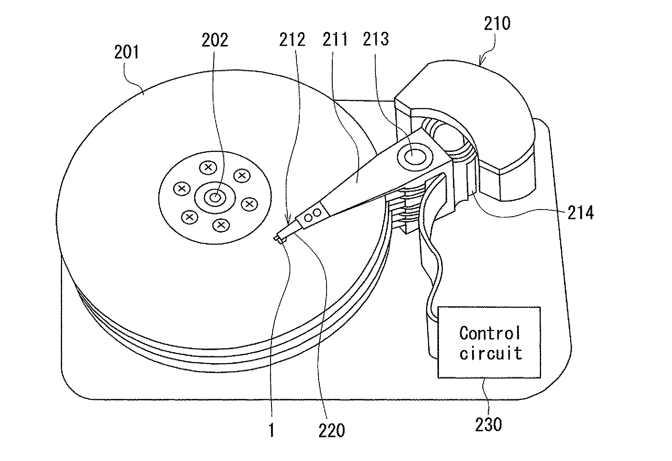
[0076]Preferred embodiments of the present invention will now be described in detail with reference to the drawings. First, reference is made to FIG. 5 to describe a magnetic disk drive that functions as a magnetic recording device according to a first embodiment of the invention. As shown in FIG. 5, the magnetic disk drive includes a plurality of magnetic disks 201 serving as a plurality of magnetic recording media, and a spindle motor 202 for rotating the magnetic disks 201. The magnetic disks 201 of the present embodiment are for use in perpendicular magnetic recording. Each magnetic disk 201 has such a structure that a soft magnetic under layer, a middle layer, and a magnetic recording layer (perpendicular magnetization layer) are stacked in this order on a disk substrate.

[0077]The magnetic disk drive further includes an assembly carriage device 210 having a plurality of driving arms 211, and a plurality of head gimbal assemblies 212 attached to respective distal ends of the dri...

second embodiment

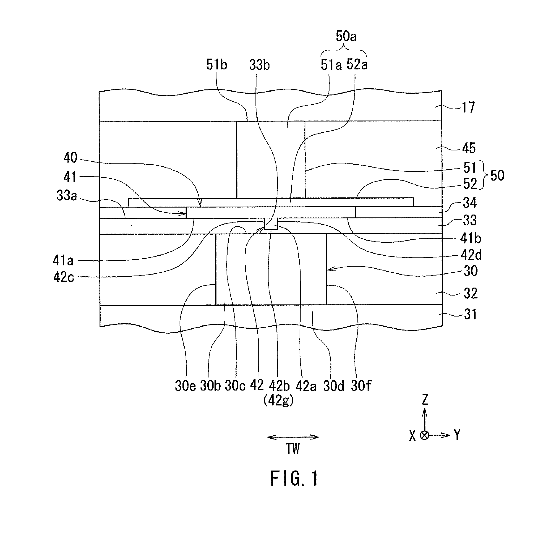
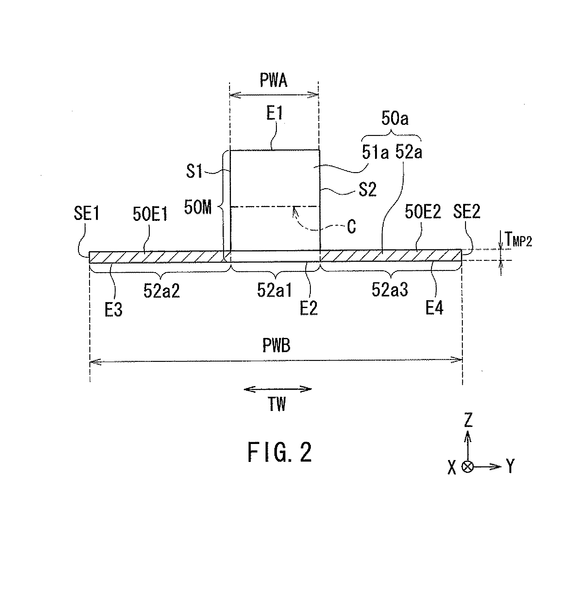
[0188]A second embodiment of the present invention will now be described. First, reference is made to FIG. 26, FIG. 28, and FIG. 29 to describe the configuration of the thermally-assisted magnetic recording head 1 according to the present embodiment. FIG. 26 is a front view showing the main part of the thermally-assisted magnetic recording head 1. FIG. 26 shows part of the medium facing surface 12a. FIG. 28 is a cross-sectional view showing the main part of the thermally-assisted magnetic recording head 1. FIG. 28 shows a cross section perpendicular to the element-forming surface 11c (see FIG. 7 and FIG. 8) and the medium facing surface 12a. FIG. 29 is a plan view showing the main part of the thermally-assisted magnetic recording head 1.

[0189]The thermally-assisted magnetic recording head 1 according to the present embodiment has a plasmon generator 80 and a magnetic pole 90, instead of the plasmon generator 40 and the magnetic pole 50 of the first embodiment. The thermally-assisted...

third embodiment

[0221]A third embodiment of the present invention will now be described. First, reference is made to FIG. 36 to describe the differences of the thermally-assisted magnetic recording head 1 according to the third embodiment from that according to the second embodiment. FIG. 36 is a front view showing the main part of the thermally-assisted magnetic recording head 1. FIG. 36 shows part of the medium facing surface 12a. The thermally-assisted magnetic recording head 1 according to the present embodiment has the plasmon generator 40 of the first embodiment, instead of the plasmon generator 80 of the second embodiment. The groove 33b of the cladding layer 33 of the present embodiment has the same shape as in the first embodiment. As in the first embodiment, the thermally-assisted magnetic recording head 1 according to the present embodiment has the dielectric layer 34.

[0222]The thermally-assisted magnetic recording head 1 further has a dielectric layer 35 disposed over the plasmon genera...


PUM

PropertyMeasurementUnit
wavelengthaaaaaaaaaa
emittable wavelength rangeaaaaaaaaaa
voltageaaaaaaaaaa

Abstract

A thermally-assisted magnetic recording head includes a magnetic pole and a heating element. The magnetic pole has a front end face located in a medium facing surface. The magnetic pole forms on a track a distribution of write magnetic field strength that peaks at a first position on the track. The heating element forms on the track a distribution of temperature that peaks at a second position on the track. The first position is located on the trailing side relative to the second position. The front end face of the magnetic pole has a main portion and first and second extended portions. The first and second extended portions are extended in the track width direction from the main portion at positions on the leading side relative to the center of the main portion in the direction of travel of a magnetic recording medium.

Description

BACKGROUND OF THE INVENTION[0001]1. Field of the Invention[0002]The present invention relates to a thermally-assisted magnetic recording head including a magnetic pole and a heating element, and to a method of manufacturing the same.[0003]2. Description of the Related Art[0004]Recently, magnetic recording devices such as magnetic disk drives have been improved in recording density, and thin-film magnetic heads and magnetic recording media of improved performance have been demanded accordingly. Among the thin-film magnetic heads, a composite thin-film magnetic head has been used widely. The composite thin-film magnetic head has such a structure that a read head section including a magnetoresistive element (hereinafter, also referred to as MR element) for reading and a write head section including an induction-type electromagnetic transducer for writing are stacked on a substrate. In a magnetic disk drive, the thin-film magnetic head is mounted on a slider that flies slightly above th...

Claims


Application Information

Patent Timeline
Patent Type & Authority Applications(United States)
IPC IPC(8): G11B5/48G11B5/858G11B5/33
CPCG11B5/314Y10T428/11G11B2005/0021G11B5/6088
Inventor HIRATA, KEITANAKA, KOSUKEROPPONGI, TETSUYA
Owner TDK CORPARATION
Why Eureka
Try Eureka