High-efficiency driving stage for phase change non-volatile memory devices

a non-volatile memory, high-efficiency technology, applied in the direction of information storage, static storage, digital storage, etc., can solve the problems of high cost, limited application range, and inability to fully exploit the advantages of the configuration described

Active Publication Date: 2013-09-05
STMICROELECTRONICS SRL
View PDF3 Cites 14 Cited by
  • Summary
  • Abstract
  • Description
  • Claims
  • Application Information

AI Technical Summary

Benefits of technology

[0025]A driving stage for a phase change non-volatile memory device may have an output driving unit which supplies an output driving current during an operation of programming of at least one memory cell. A driving-control unit receives an input current and generates at output a first control signal that controls supply of the output driving current by the output driving unit in such a way that a value of this current has a desired relation with the input current. A level-shifter element, set between the output of the driving-control unit and a control input of the output driving unit, determines a level shift of the voltage of the first control signal so as to supply to the control input of the output driving unit a second control signal, having a voltage value that is increased with respect to, and is a function of, the first control signal.

Problems solved by technology

However, the configuration described also has some limitations that do not enable full exploitation of the advantages thereof.
Moreover, it may be required that all the transistors in the circuit are of the high-voltage type to withstand the high voltage values present across their terminals, which, combined with the high requirements of output current, entails the use of transistors of large dimensions (with large thicknesses of the corresponding oxides), and high costs, and once again a considerable occupation of space.
Given that the entire driving stage 6 is supplied by the charge-pump stage 10, the latter must be sized so as to meet the high current requirements thereof, and in particular the inefficiency of the driving stage 6 results in a high consumption of current required of the charge-pump stage 10.

Method used


Image

  • High-efficiency driving stage for phase change non-volatile memory devices
  • High-efficiency driving stage for phase change non-volatile memory devices
  • High-efficiency driving stage for phase change non-volatile memory devices

Examples


Embodiment Construction

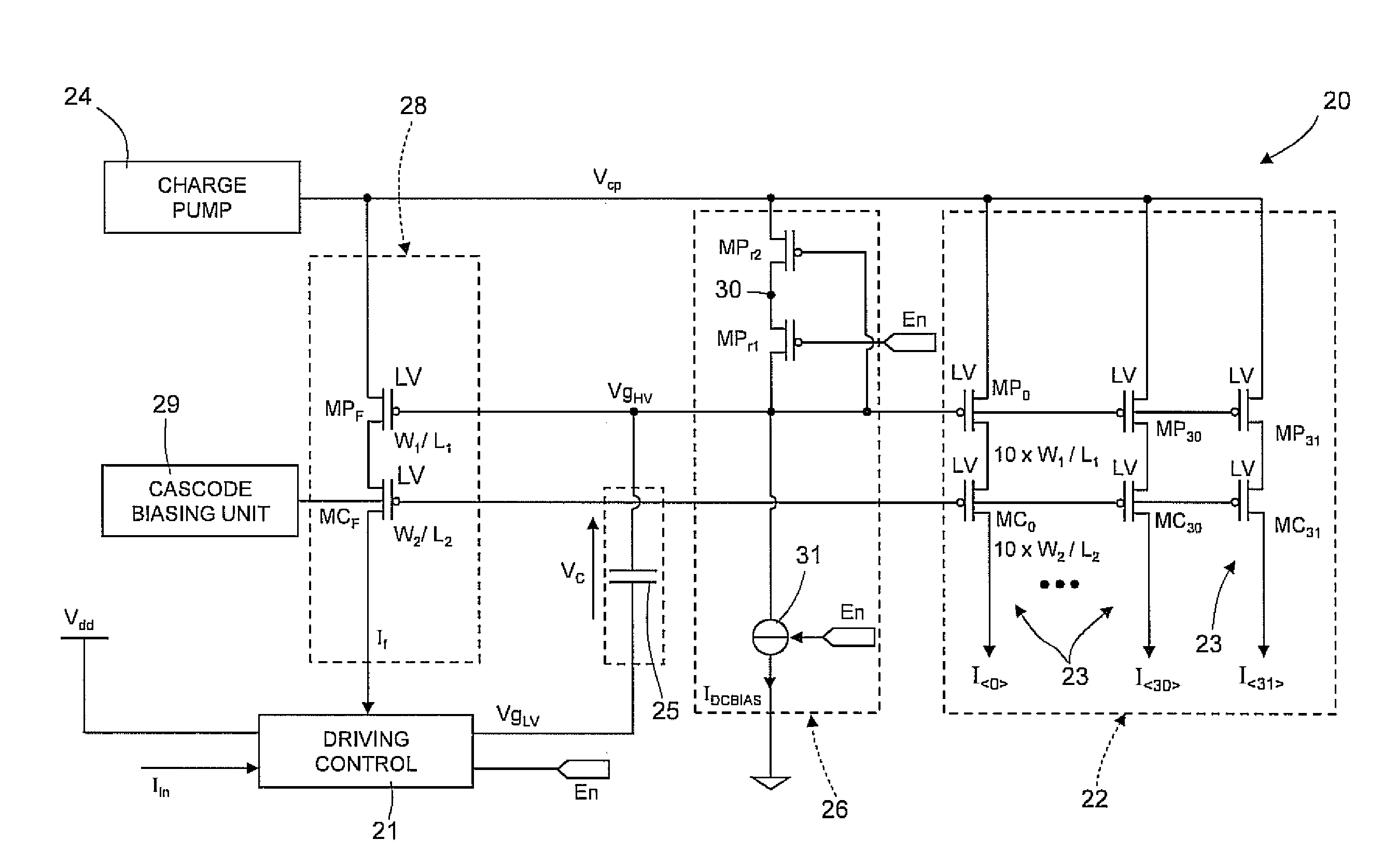
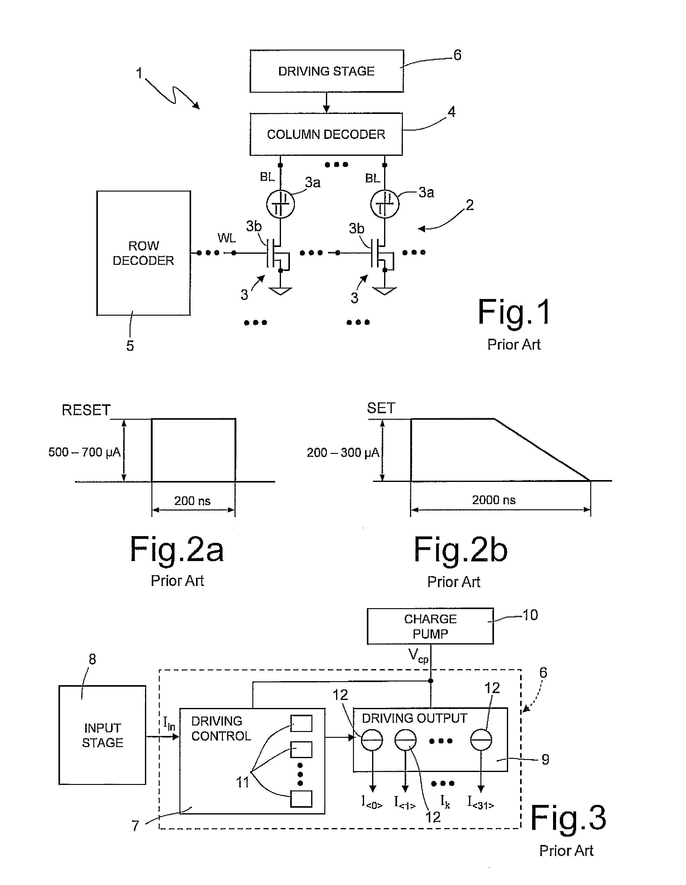
[0035]As shown in FIG. 5, according to one embodiment of the invention, a driving stage 20 for a phase change non-volatile memory device (for example, of the type described with reference to FIG. 1, which for this reason is not described again) includes a driving-control unit 21, which receives, on a first low-impedance input, an input current Iin, with an appropriate value that is a function of a specific memory operation, and an output driving unit 22 including a plurality of driving sub-units 23 (and represented schematically as controlled current generators), each of which, is appropriately supplied by a charge-pump stage 24, and supplies on a respective output a respective output driving current Ik, having a value amplified by a factor β with respect to the input current Iin, according to the relation: Ik=Iin·β.

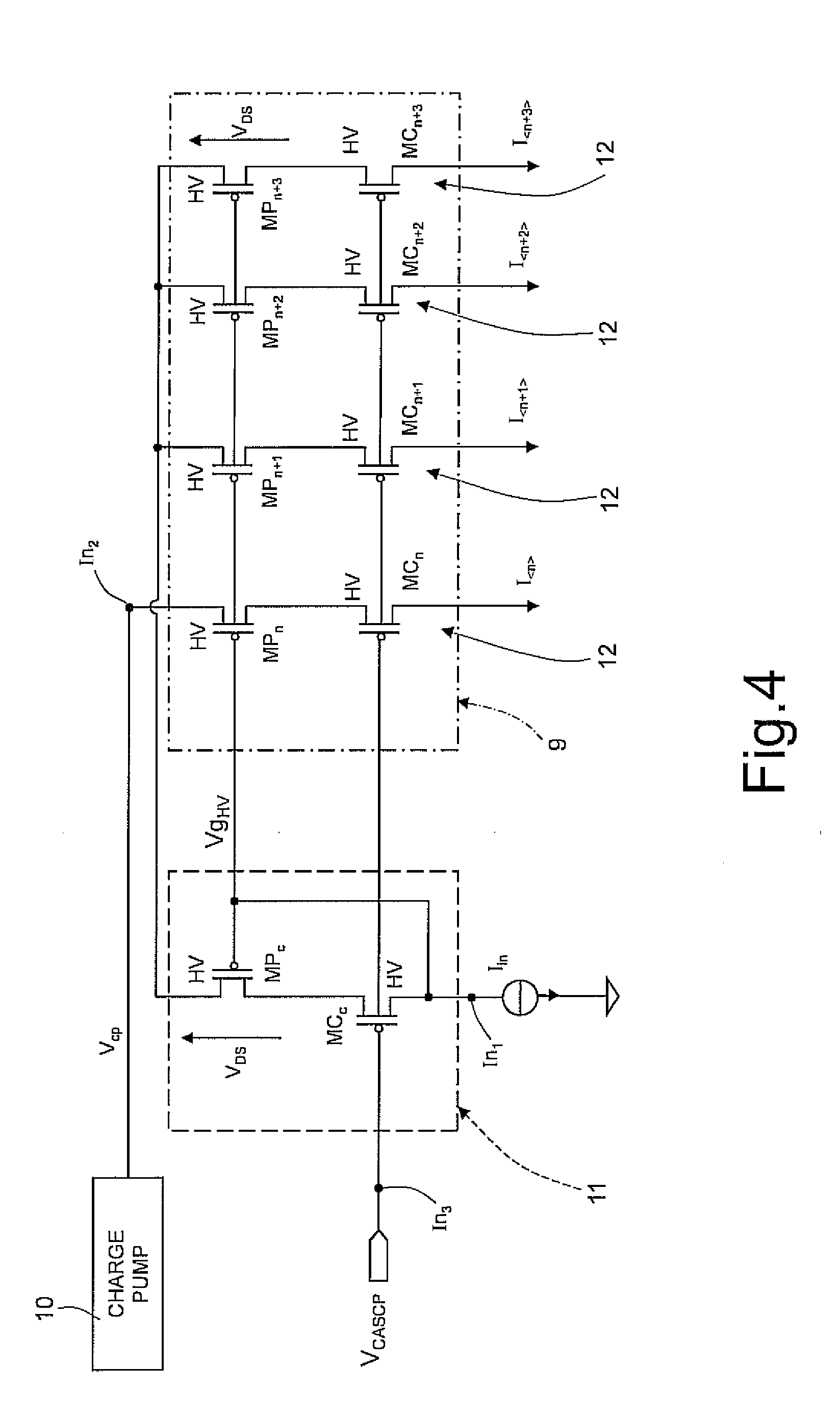
[0036]As will be described in detail hereinafter, in addition to receiving a boosted voltage Vcp from the charge-pump stage 24, the output driving unit 22 receives at in...


PUM


Abstract

A driving stage for a phase change non-volatile memory device may have an output driving unit which supplies an output driving current during an operation of programming of at least one memory cell. A driving-control unit receives an input current and generates at output a first control signal that controls supply of the output driving current by the output driving unit in such a way that a value of this current has a desired relation with the input current. A level-shifter element, set between the output of the driving-control unit and a control input of the output driving unit, determines a level shift of the voltage of the first control signal so as to supply to the control input of the output driving unit a second control signal, having a voltage value that is increased with respect to, and is a function of, the first control signal.

Description

FIELD OF THE INVENTION[0001]The present invention relates to a driving stage for phase change non-volatile memory devices, designed for the supply of driving currents during programming operations of the memory cells.BACKGROUND OF THE INVENTION[0002]As it is known, phase change non-volatile memories, so-called ePCMs (embedded Phase Change Memories), represent a new generation of integrated memories, in which, to store information, the characteristics of materials having the property of switching between phases having different electrical characteristics are exploited. For example, these materials can switch between an amorphous, disorderly, phase and a crystalline or polycrystalline, orderly, phase, and the two phases are associated to resistivities of considerably different value, and consequently to a different value of a datum stored. For example, the elements of the VI group of the periodic table, such as tellurium (Te), selenium (Se), or antimony (Sb), referred to as chalcogeni...

Claims


Application Information

Patent Timeline
Patent Type & Authority Applications(United States)
IPC IPC(8): G11C13/00
CPCG11C5/145G11C5/147G11C13/0004G11C13/0069G11C13/0038
Inventor CONTE, ANTONINOGIAQUINTA, MARIACHIARAMONTE, LOREDANA
Owner STMICROELECTRONICS SRL
Why Eureka
Try Eureka