Radiation generating apparatus and radiation imaging apparatus
a radiation generation apparatus and radiation imaging technology, applied in the direction of material analysis using wave/particle radiation, instruments, x-ray tube targets and convertors, etc., can solve the problems of difficult generation of high-energy radiation, difficulty in size and weight reduction, etc., to achieve long-term driving for radiation generation and suppress the effect of increasing the temperature of the transmitting substra
- Summary
- Abstract
- Description
- Claims
- Application Information
AI Technical Summary
Benefits of technology
Problems solved by technology
Method used
Image

Examples
first embodiment
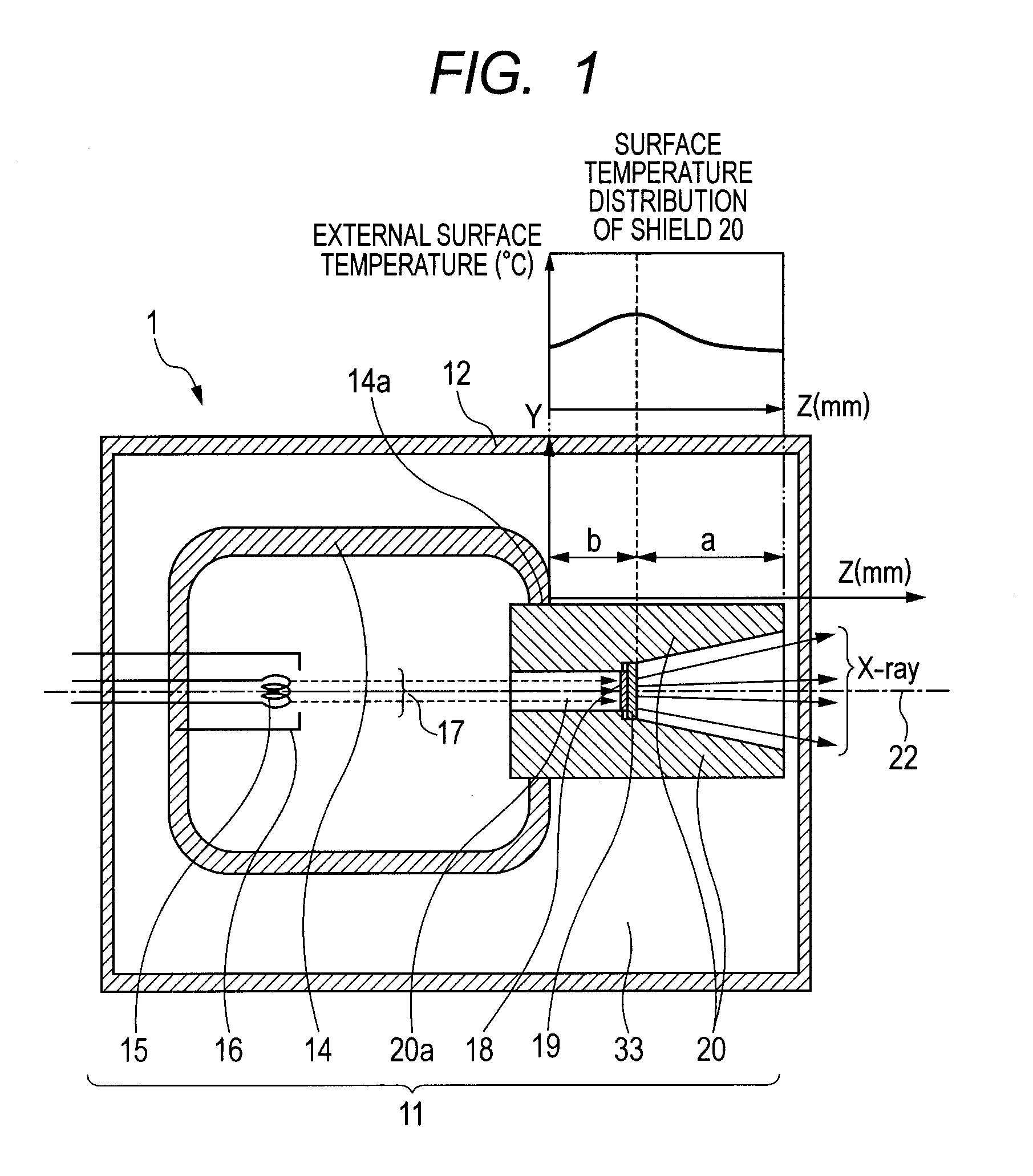
[0016]First, a radiation generating apparatus according to a first embodiment of the present invention will be described with reference to FIG. 1. FIG. 1 illustrates a schematic cross-sectional diagram of a radiation generating apparatus using a transmission type radiation generating tube according to the present embodiment, and a temperature distribution diagram at an external surface of a shield. The schematic cross-sectional diagram in FIG. 1 indicates a Z-Y cross-section with a direction of a center line of an electron flux (electron flux center line 22) as a Z-axis direction.
[0017]As illustrated in FIG. 1, a radiation generating apparatus 1 according to the present embodiment includes a transmission type radiation generating tube 11, and the transmission type radiation generating tube 11 is housed inside a holding container 12. The rest of the space inside the holding container 12 except the space in which the transmission type radiation generating tube 11 is housed is charged ...
second embodiment
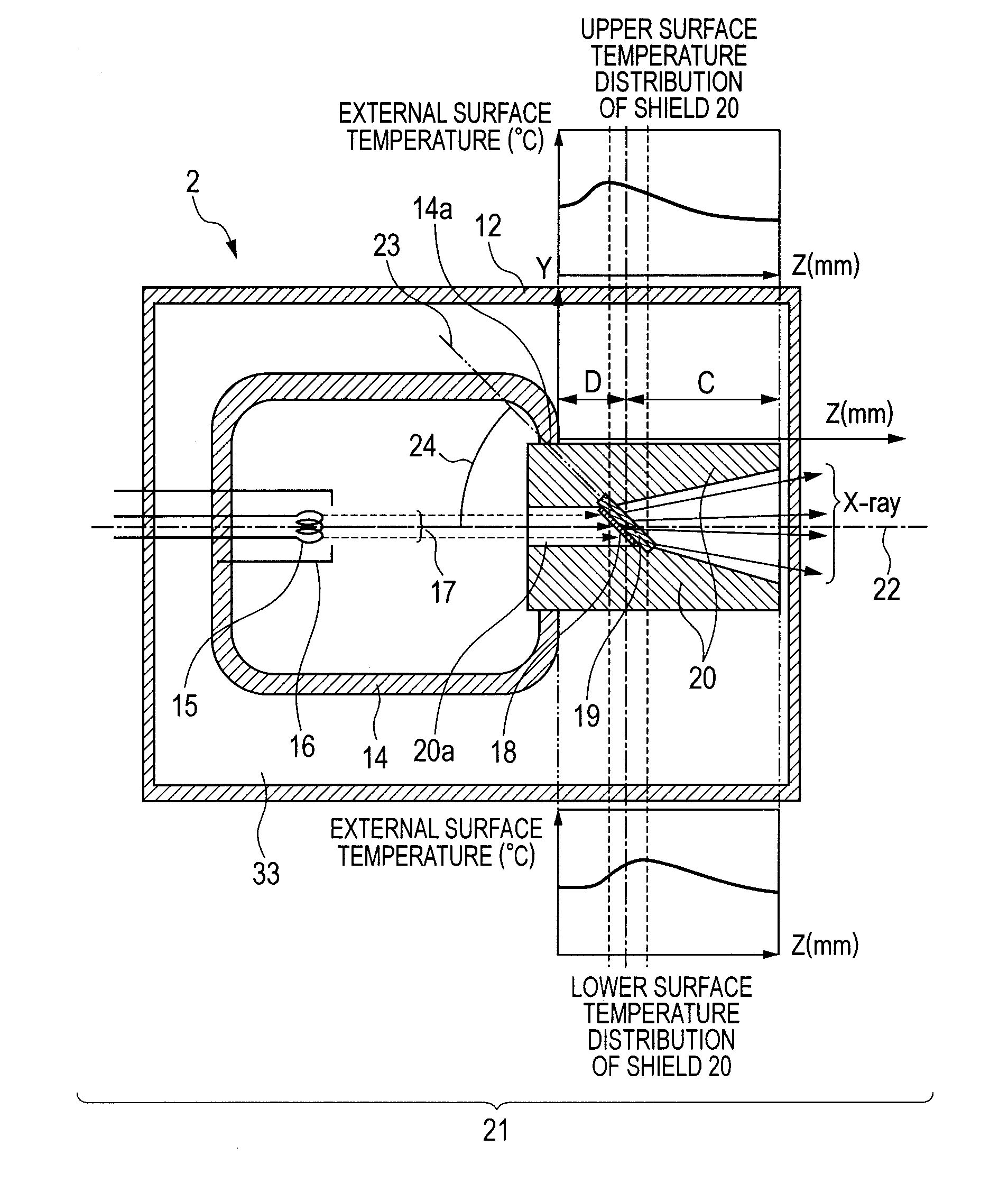
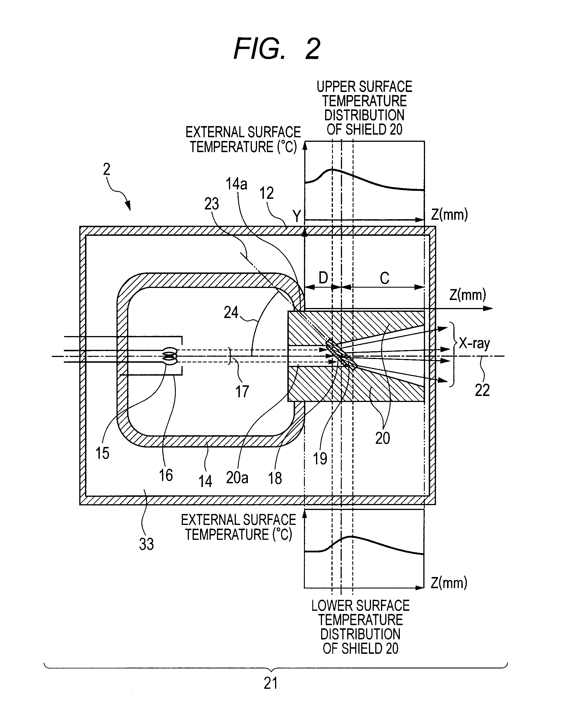
[0038]Next, a radiation generating apparatus according to a second embodiment of the present invention will be described with reference to FIG. 2. FIG. 2 illustrates a schematic cross-sectional diagram of a radiation generating apparatus using a transmission type radiation generating tube according to the present embodiment, and a temperature distribution diagram at an external surface of a shield. For a description of components that are the same as those of the radiation generating apparatus 1 according to the first embodiment, reference numerals that are the same as those of the first embodiment are used.
[0039]As illustrated in FIG. 2, a radiation generating apparatus 2 according to the present embodiment is different from the first embodiment in that a transmitting substrate 19 is arranged on a plane not perpendicular to, but inclined with regard to a passage 20a of a shield 20. More specifically, a substrate inclination angle 24 corresponding to an angle formed by an electron f...
third embodiment
[0043]Next, a third embodiment of a radiation generating apparatus according to the present invention will be described with reference to FIG. 3. FIG. 3 illustrates a schematic cross-sectional diagram of a radiation generating apparatus using a transmission type radiation generating tube according to the present embodiment, and a temperature distribution diagram at an external surface of a shield. The description will be provided using reference numerals that are the same as those of the radiation generating apparatus 1 according to the first embodiment for components that are the same as those of the first embodiment.
[0044]As illustrated in FIG. 3, the radiation generating apparatus 3 according to the present embodiment is different from the first embodiment in that an cooling medium 33 guiding portion 32 for guiding an cooling medium 33 into a shield 20 is provided. The cooling medium 33 guiding portion 32 can be arranged at a position on the electron emitting source side relative...
PUM
 Abstract
Description
Claims
Application Information
 - R&D
- Intellectual Property
- Life Sciences
- Materials
- Tech Scout
- Unparalleled Data Quality
- Higher Quality Content
- 60% Fewer Hallucinations
Browse by: Latest US Patents, China's latest patents, Technical Efficacy Thesaurus, Application Domain, Technology Topic, Popular Technical Reports.
© 2025 PatSnap. All rights reserved.Legal|Privacy policy|Modern Slavery Act Transparency Statement|Sitemap|About US| Contact US: help@patsnap.com