Backup wall reinforcement with t-type siderail

a technology of reinforcement and siderail, which is applied in the direction of walls, building components, shock-proofing, etc., can solve the problems that the current state of the art does not meet the need for a hybrid anchor and reinforcement assembly that provides a 3-axis restraint system, and none of these devices offers a backup wall reinforcement and anchor. , to achieve the effect of limiting veneer displacement, low unit cost and economical manufactur

Inactive Publication Date: 2013-09-12
MITEK HLDG INC
View PDF0 Cites 44 Cited by
  • Summary
  • Abstract
  • Description
  • Claims
  • Application Information

AI Technical Summary

Benefits of technology

[0021]An alternative veneer tie or veneer anchor is a metal stamping designed to connect with and be secured over the anchor and within the exterior wall bed joint. The alternative veneer tie contains a slot in the connector portion that is dimensioned to allow the veneer tie to be placed over the anchor and manually rotated or twisted 90 degrees for securement on the anchor. The veneer tie optionally contains a securement notch that snap fits onto the wall anchor. Upon securement on the anchor, the free end of the veneer tie spans the cavity and inserted within the bed joint of the exterior wall. For greater seismic protection, the veneer tie is notched to secure a reinforcement wire within the veneer tie and the bed joint of the exterior wall. For greater displacement protection, the veneer tie section that spans the cavity is offset where the tie section abuts the interior of the exterior wall.
[0024]It is a further object of the present invention to provide an anchoring system comprising a limited number of component parts that are economical of manufacture resulting in a low unit cost.
[0025]It is yet another object of the present invention to provide an anchoring system which is easy to install and meets seismic and shear resistance requirements.
[0026]It is another object of the present invention to provide labor-saving devices to simplify seismic-type installations of brick and stone veneer and the securement thereof to a backup wall.

Problems solved by technology

Besides earthquake protection, the failure of several high-rise buildings to withstand wind and other lateral forces has resulted in the incorporation of a requirement for continuous wire reinforcement in the Uniform Building Code provisions.
However, none of these devices offers a hybrid backup wall reinforcement and anchor that when combined with the disclosed veneer tie provides reinforcement and 3-axis displacement protection.
Limiting veneer tie movement protects against movement and shifting of the exterior wall, which is a cause of structural damage.
Accordingly, while several distinct devices were developed to provide a connection between the backup and exterior walls, the current state of the art does not fulfill the need for a hybrid anchor and reinforcement assembly that provides a 3-axis restraint system.

Method used


Image

  • Backup wall reinforcement with t-type siderail
  • Backup wall reinforcement with t-type siderail
  • Backup wall reinforcement with t-type siderail

Examples


first embodiment

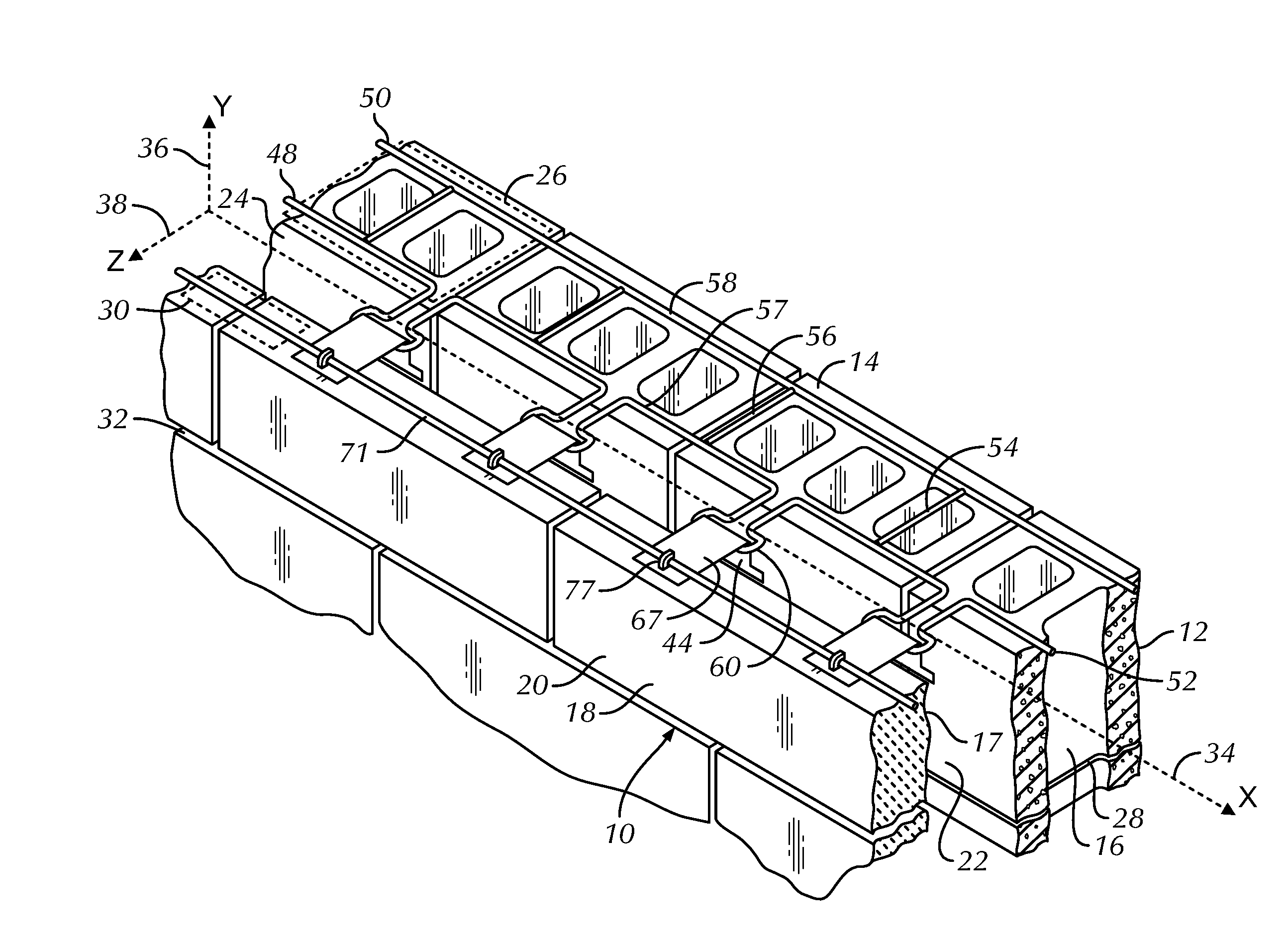
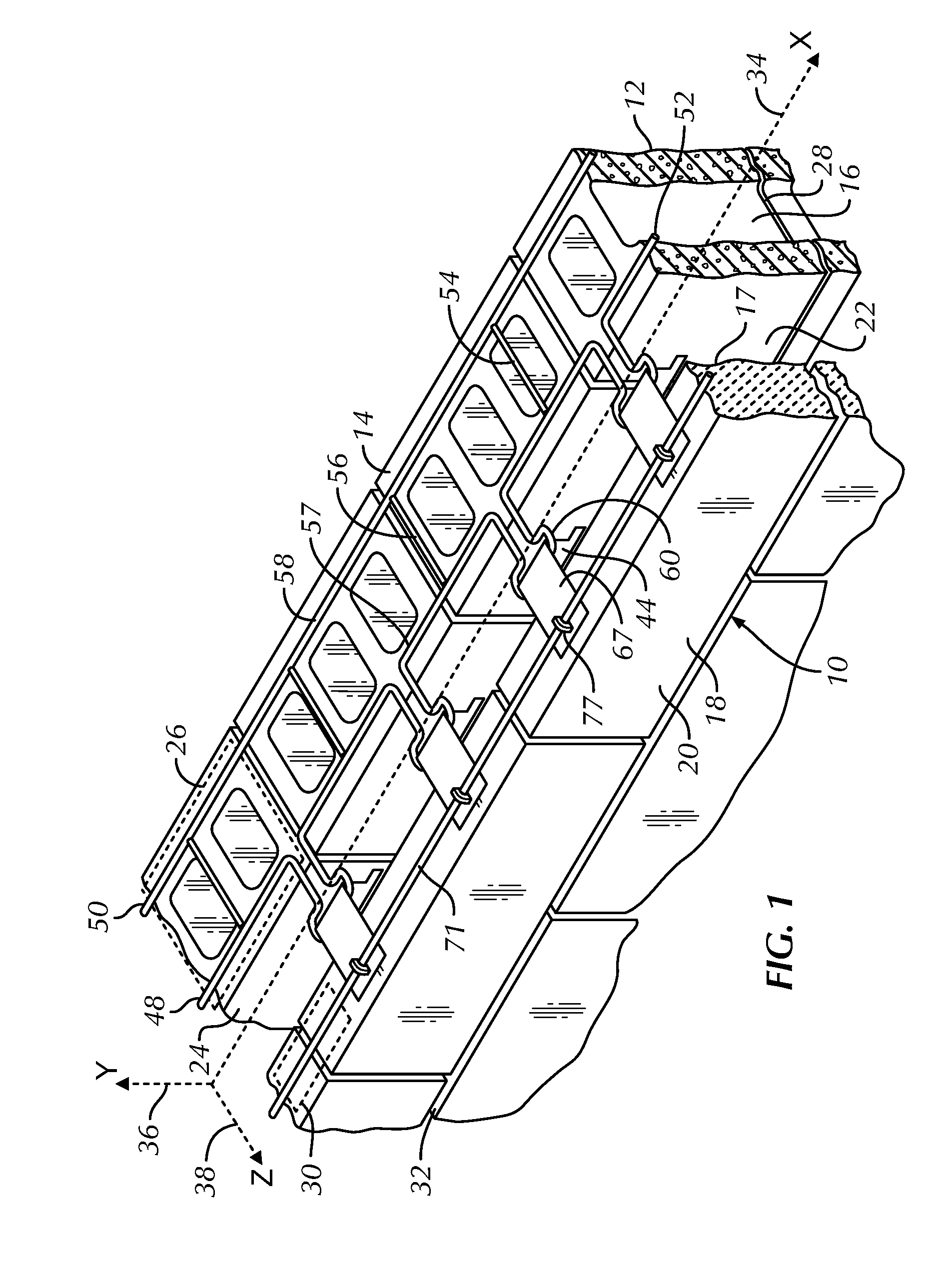
[0050]Referring now to FIG. 1 through 5, an anchoring system utilizing a backup wall reinforcement with T-type siderails is shown and is referred to generally by the numeral 10. In this embodiment, a masonry wall structure 12 is shown having a backup wall or exterior wythe 14 of masonry blocks 16 and a facing wall, exterior wall or veneer 18 of facing brick or stone 20. Between the backup wall 14 and the facing wall 18, a cavity 22 is formed, which cavity 22 extends outwardly from the interior surface 24 of backup wall 14. The backup wall 14 and the facing wall 18 have interior surfaces or sides 24 and 17, respectively that face the cavity 22.

[0051]In this embodiment, successive bed joints 26 and 28 are formed between courses of blocks 16 and the joints are substantially planar and horizontally disposed. Also, successive bed joints 30 and 32 are formed between courses of facing brick 20 and the bed joints are substantially planar and horizontally disposed. For each structure, the be...

second embodiment

[0055]The veneer tie 44 contains a free end portion 47. The free end 47 includes a cavity portion 67 and an insertion portion or bed joint portion 77. The cavity portion 67 spans the cavity 22 and the insertion portion is dimensioned for disposition within the bed joint 30 of the facing wall 18. When inserted in the facing wall 18, the free end 47 is in a substantially horizontal plane with the bed joint 30. The bed joint portion 77 contains one or more reinforcement notches 69 to secure a reinforcement wire 71 within the bed joint portion 77 for embedment in the bed joint 30 of the facing wall 18. The inclusion of the reinforcement wire 71 completes the seismic construct. The veneer tie 44 optionally contains an offset (not shown) similar to that shown in the second embodiment below. The free end 47 optionally contains apertures 73 to limit thermal transfer. Optionally, insulation (not shown) may be added to the interior 24 of the backup wall 14. If insulation is installed, the str...

third embodiment

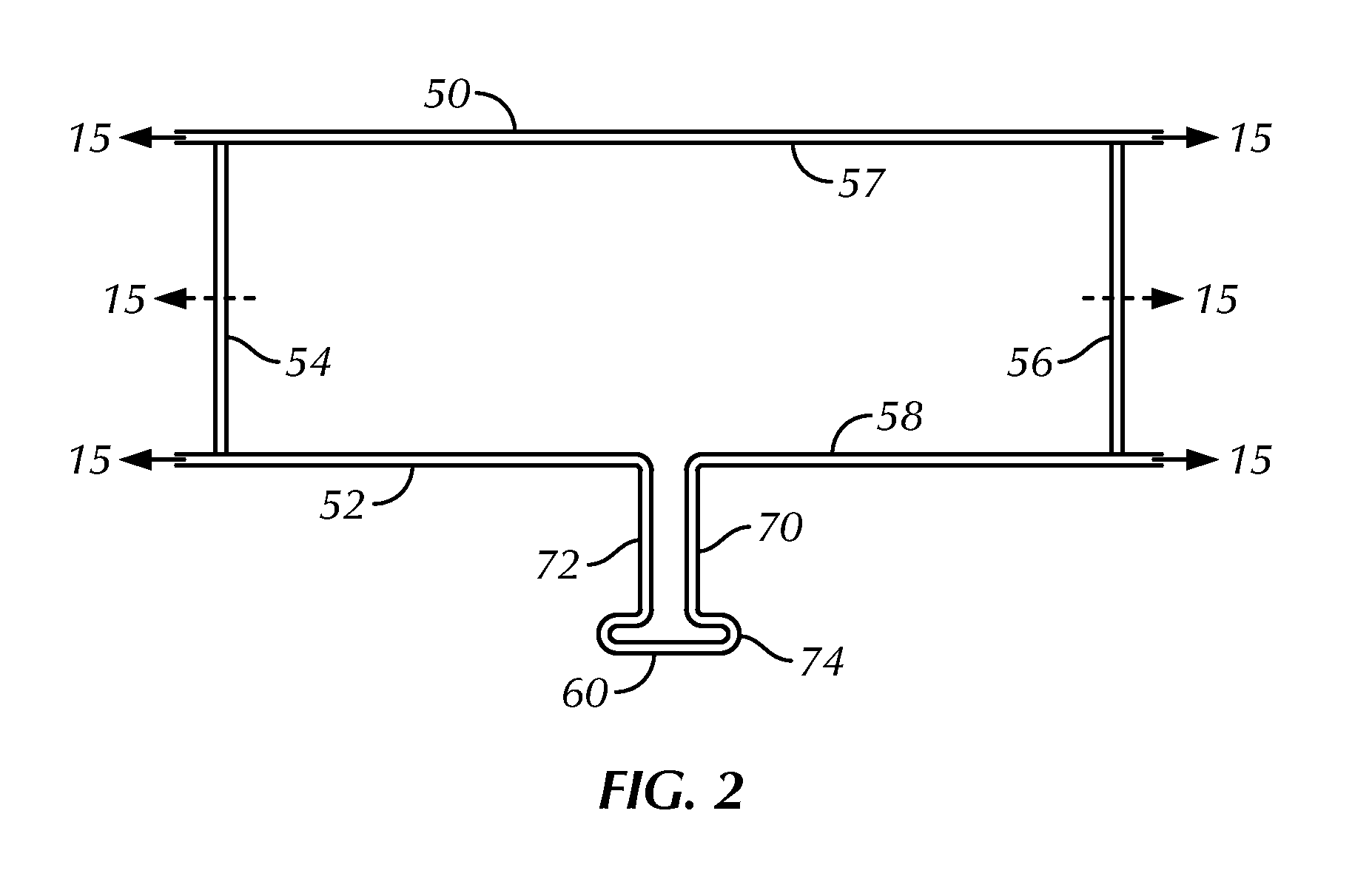
[0067]Referring now to FIGS. 11 through 13, a backup wall reinforcement with T-type siderails of this invention is shown and is referred to generally by the numeral 210. In this embodiment, a cavity wall structure is not shown but is substantially similar to the cavity wall structure shown in FIGS. 1 and 6. The anchoring system 210 includes a reinforcement device or wall reinforcement portion 248 with an integral anchor or wall anchor portion 260. The reinforcement device 248 is embedded in the bed joints and includes two side rails or wires 250, 252 which are parallel to each other. One or more intermediate wires 254, 256 are attached to the interior sides or surfaces of 257, 258 of the side rails 250, 252 and maintain the parallelism of the side rails 250, 252. The intermediate wires form a ladder 254, 256 configuration or optionally, a truss configuration (not shown). The longitudinal axis of the intermediate wires 254, 256 and the side rails 250, 252 is substantially similar to ...


PUM


Abstract

A backup wall reinforcement with T-type siderail anchoring system is described for use in masonry cavity walls. The reinforcement and integral anchor is hybrid device installed within the backup wall and interlocked with novel veneer ties. The novel veneer ties are manually connected through swinging or twisting the veneer ties until the veneer ties are interlocked with the anchor. Once interlocked, lateral and vertical veneer tie movement is limited strengthening the cavity wall structure. The inclusion of a reinforcement wire within the veneer ties and the exterior wall provides a seismic structure.

Description

BACKGROUND OF THE INVENTION[0001]1. Field of the Invention[0002]This invention relates to reinforcement and anchor assemblies for use in masonry backup walls and, in particular, cavity wall constructs with backup and veneer walls that require superior anchoring properties. The backup wall reinforcement is a hybrid anchoring system which includes a reinforcement with an integrated anchor for connection to an interlocking veneer tie which provides a 3-axis restraint system, limiting movement and exterior wall displacement.[0003]2. Description of the Prior Art[0004]Masonry, the building of structures from individual units laid in and bound together by mortar, is commonly used for the construction of buildings. Such widespread use is the result of the high durability, compressive strength, thermal mass and heat resistance of the masonry building materials. Because masonry construction requires extensive manual labor and individual building materials, the quality of the masonry construct...

Claims


Application Information

Patent Timeline
Patent Type & Authority Applications(United States)
IPC IPC(8): E04B1/41E04B1/98
CPCE04B2002/0282E04B1/4185
Inventor HOHMANN, JR., RONALD P.
Owner MITEK HLDG INC
Why Eureka
Try Eureka