Throttle valve system for an engine

a technology of valve system and engine, which is applied in the direction of electric control, machines/engines, combustion air/fuel air treatment, etc., can solve the problem of adding significant cost to the electronic throttle control system, and achieve the effect of reducing the production cost of the engin

Inactive Publication Date: 2013-09-12
FORD GLOBAL TECH LLC
View PDF11 Cites 35 Cited by
  • Summary
  • Abstract
  • Description
  • Claims
  • Application Information

AI Technical Summary

Benefits of technology

[0005]The default open position of the second throttle provides intake air to the engine so that the first throttle valve may be designed with a default closed position. In other words, the default open position of the second throttle valve provides similar functionality of the fail-safe mechanism with regard to providing intake air to the engine. Thus, by providing the second throttle valve with the default open position, the mechanism to hold the first throttle valve at a precise default open position may be eliminated, while maintaining similar functionality. In this way, the product

Problems solved by technology

Due to this electronic control over the throttle position, the throttle can move regardless of a position of an accelerator pedal, which can be problematic if the ETC is unpowered.
For exampl

Method used


Image

  • Throttle valve system for an engine
  • Throttle valve system for an engine
  • Throttle valve system for an engine

Examples


Embodiment Construction

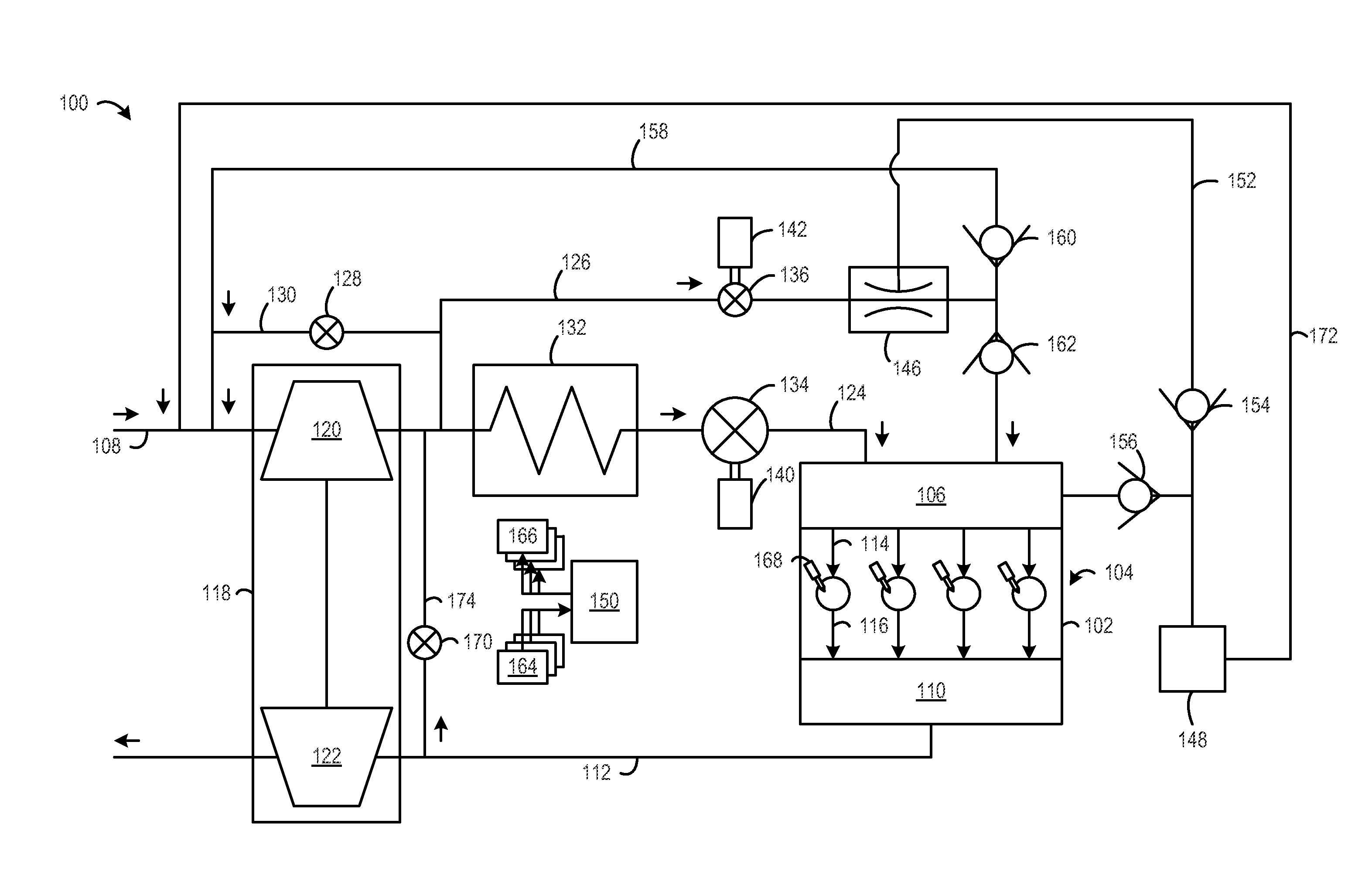
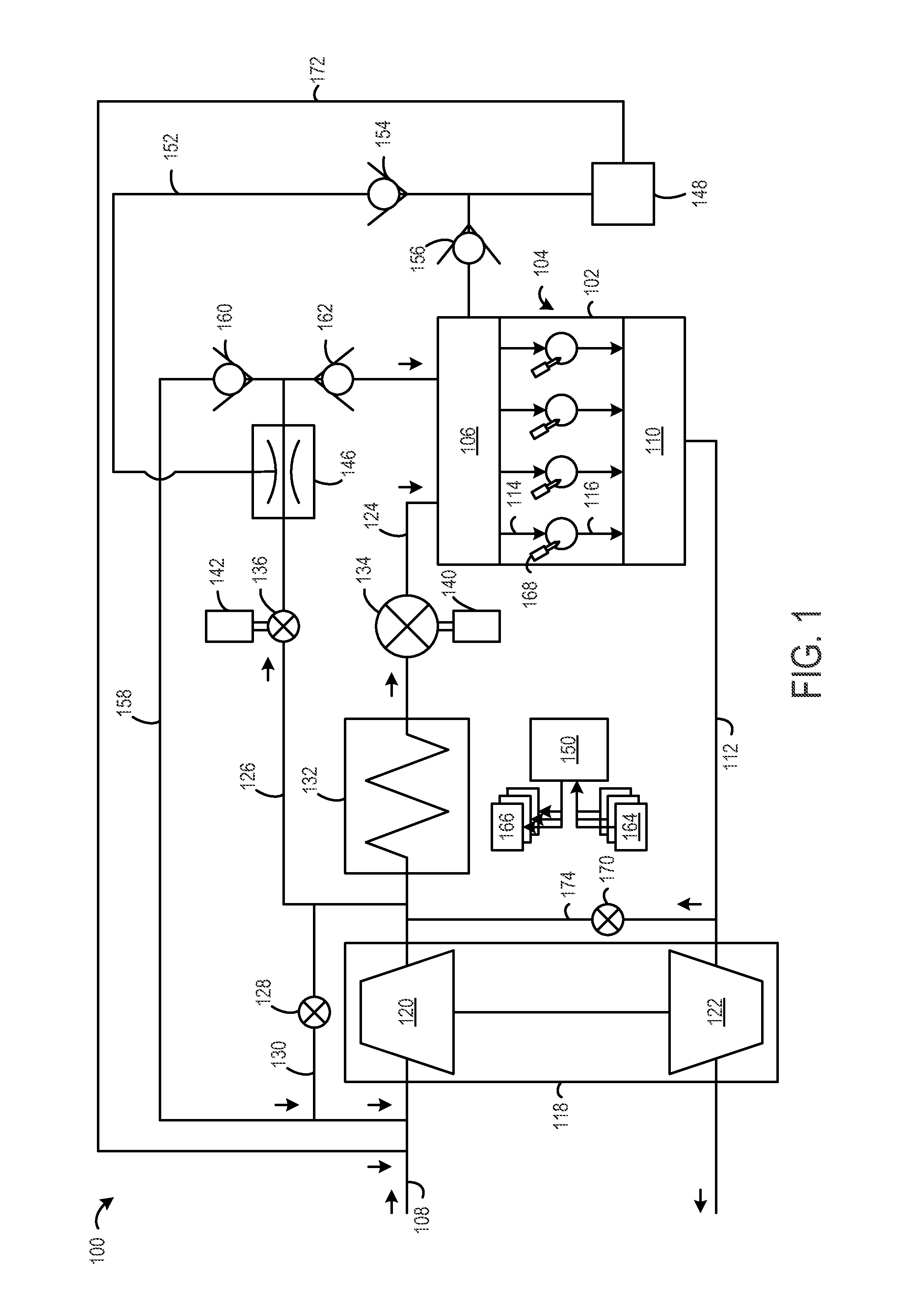
[0014]The following description relates to an electronic throttle control system in an engine that includes a first throttle valve and a second throttle valve. The first throttle valve and the second throttle valve may be arranged in such a way that the second throttle valve provides intake air flow when in a default position that allows the first throttle to a have a default position that is closed. This arrangement allows for the elimination of mechanisms for positioning the first throttle valve a precise default open position, which reduces the cost of the electronic throttle system.

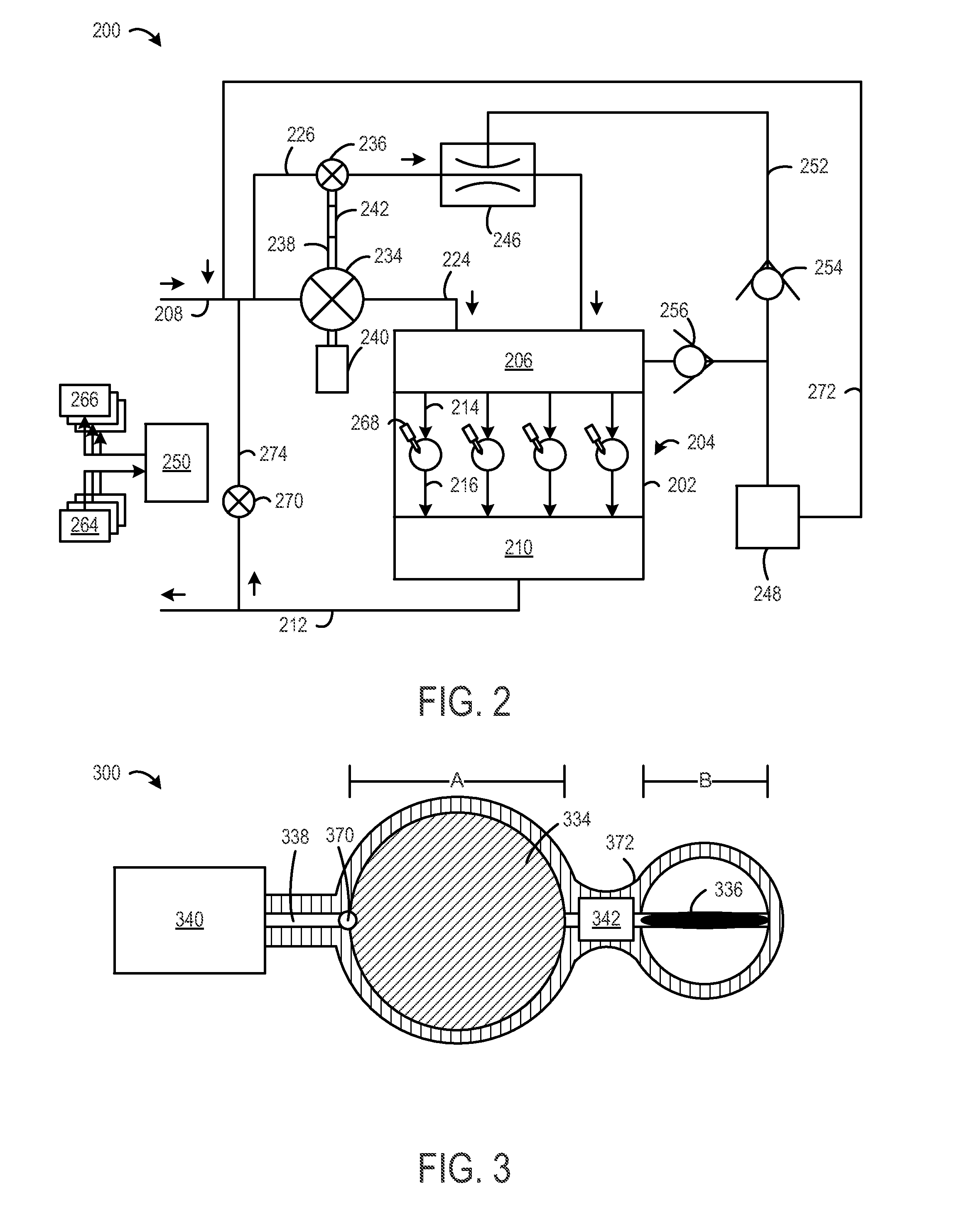
[0015]Furthermore, the second throttle valve may provide air flow to a venturi pump to provide vacuum for a vacuum consumption device. In this case, the arrangement of the first throttle valve is simplified by the addition of the second throttle valve, and the second throttle valve serves the dual purpose of controlling air flow to the engine and the venturi pump. In this way, the second throttle valv...


PUM


Abstract

An embodiment of an engine is described. The engine includes a first throttle valve. The first throttle valve is provided in a first intake passage coupled to an intake manifold. The first throttle valve has a default closed position. The engine further includes a second throttle valve. The second throttle valve is provided in a second intake passage coupled to the intake manifold. The second throttle valve has a default open position. The engine further includes a venturi pump that is provided between the second throttle valve and the intake manifold. When the second throttle valve is in the default open position, intake air flows through the venturi pump.

Description

BACKGROUND AND SUMMARY[0001]Vehicles may use electronic throttle control (ETC) to adjust a throttle position in an internal combustion engine. Further, a desired throttle position may be determined by various sensors such as an accelerator pedal position sensor, an engine speed sensor, a vehicle speed sensor, etc. Once the desired throttle position is calculated, an electric motor within the ETC is driven to the desired throttle position. Further, ETC is integrated with other electronic features such as cruise control, traction control, stability control, and other controls that contribute to torque management. Due to this electronic control over the throttle position, the throttle can move regardless of a position of an accelerator pedal, which can be problematic if the ETC is unpowered. Therefore, ETC is often integrated with an ability to assume a default position such that at least some intake air can reach the engine to avoid stalling.[0002]For example, U.S. Pat. No. 6,155,533 ...

Claims


Application Information

Patent Timeline
IPC IPC(8): F02D9/00F02D9/08
CPCY02T10/146F02D9/02F02B29/0418F02D9/1095F02D11/107F02D23/02F02D41/0002F02M35/10118F02M35/10229F02M35/108F02M26/05Y02T10/12Y02T10/40
Inventor PURSIFULL, ROSS DYKSTRAULREY, JOSEPH NORMAN
Owner FORD GLOBAL TECH LLC
Why Eureka
Try Eureka