

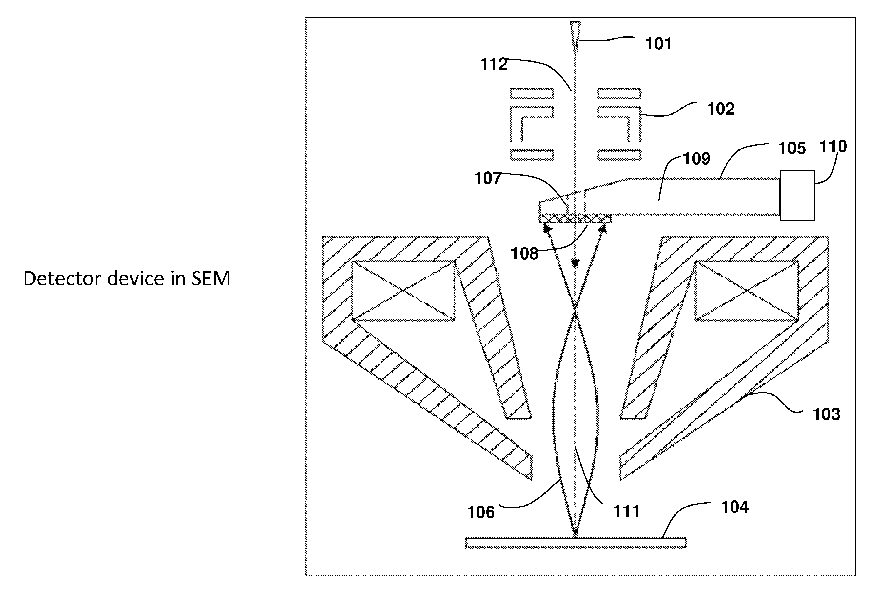
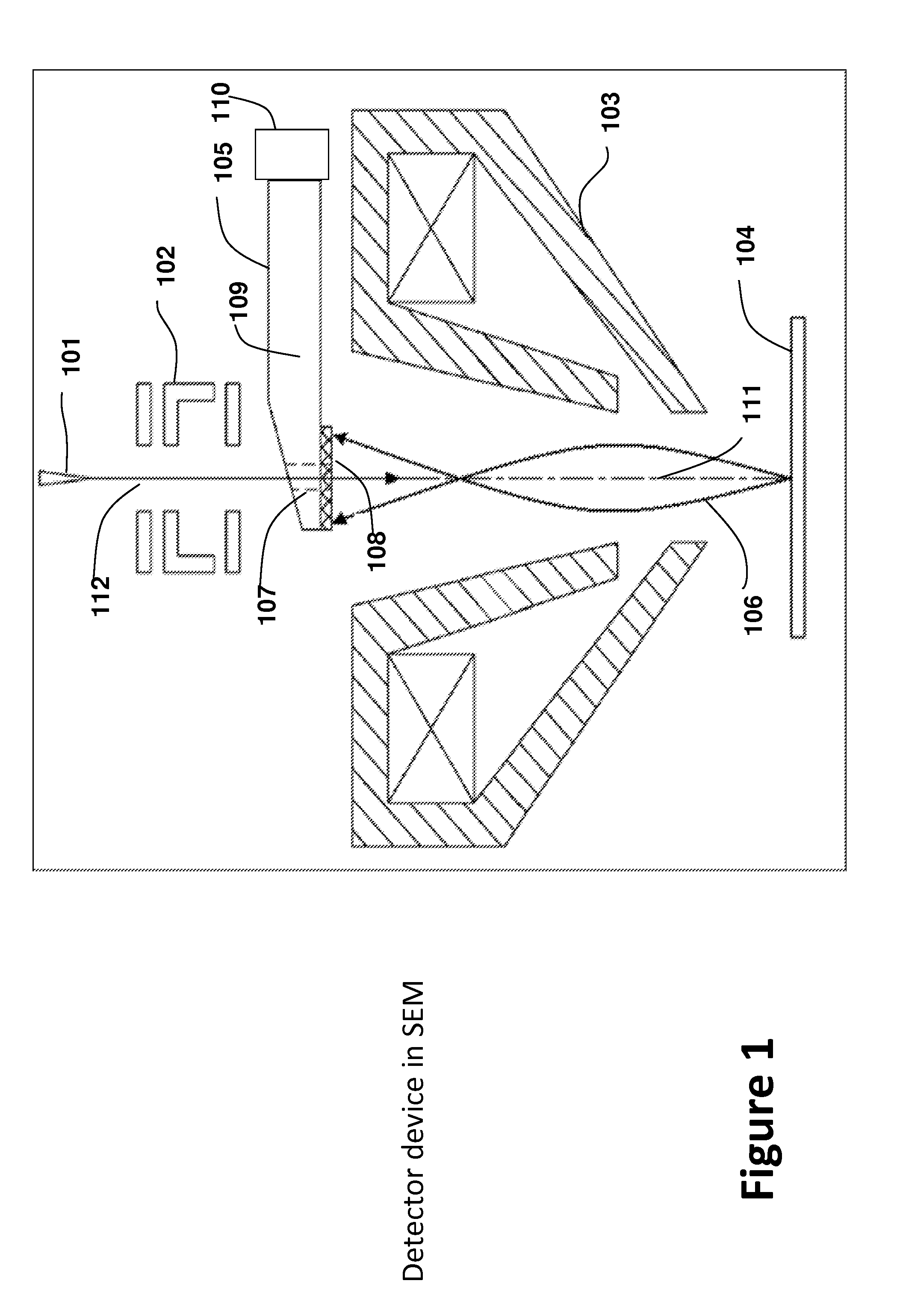
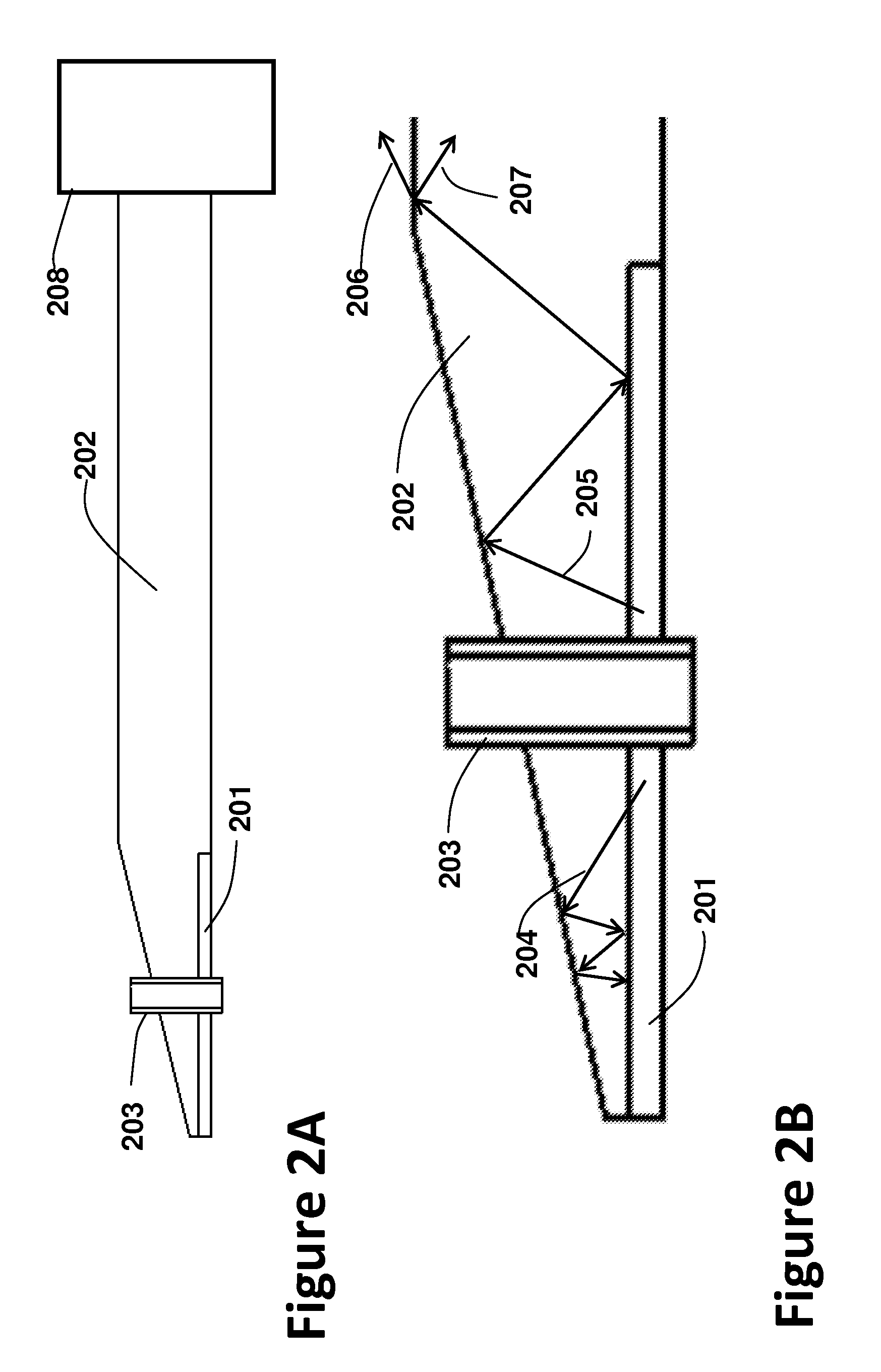
High efficiency secondary and back scattered electron detector
a secondary and electron detector technology, applied in the field of charged particle detection devices, can solve the problems of low efficiency of electrons to light signal conversion and light signal collection, introduce a larger electric noise into the image, etc., and achieve the effects of improving light collection efficiency, and improving light collection efficiency
- Summary
- Abstract
- Description
- Claims
- Application Information
AI Technical Summary
Benefits of technology
Problems solved by technology
Method used
Image

Examples
Embodiment Construction
[0043]Various example embodiments of the present invention will now be described more fully with reference to the accompany drawings in which some example embodiments of the invention are shown. Without limiting the scope of the protection of the present invention, all the description and drawings of the embodiments will exemplarily be referred to an electron source and scanning electron microscope. However, the embodiments are not be used to limit the present invention to specific charged particle sources and specific electron microscope field.
[0044]The descriptions below will focus on using electron beam, which is a kind of charged particles. In the drawings, relative dimensions of each component and among every component may be exaggerated for clarity. Within the following description of the drawings the same reference numbers refer to the same components or entities, and only the differences with respect to the individual embodiments are described.
[0045]The first embodiment of p...
PUM
 Abstract
Description
Claims
Application Information