Optical Amplifier and Optical Transmission System

a technology of optical amplifier and optical transmission system, which is applied in electromagnetic transmission, electromagnetic transmission, and semiconductor lasers. it can solve the problems of optical fiber or the like being adversely affected, image quality may be degraded, etc., and achieve the effect of reducing power consumption, improving transmission system communication quality, and saving the cost of system maintenan

Inactive Publication Date: 2013-09-12
FURUKAWA ELECTRIC CO LTD
View PDF17 Cites 27 Cited by
  • Summary
  • Abstract
  • Description
  • Claims
  • Application Information

AI Technical Summary

Benefits of technology

[0019]With such a structure, by improving a communication quality of the transmission system and reducing the power consumption, the cost required for the maintenance of the system can be saved.
[0020]According to an optical amplifying apparatus and an optical transmission system of an aspect of the invention, analog characteristics can be improved while reducing the power consumption.

Problems solved by technology

In amplifying a video in an optical amplifying apparatus using the aforementioned optical fiber, an image quality may be degraded by factors including a noise and a signal distortion that occur in the optical amplifying apparatus.
When such a residual pump light is generated, the optical fiber or the like may be adversely affected by heat and energy originating from the residual pump light.

Method used


Image

  • Optical Amplifier and Optical Transmission System
  • Optical Amplifier and Optical Transmission System
  • Optical Amplifier and Optical Transmission System

Examples


Embodiment Construction

[0031]An embodiment of the present invention will now be described.

[0032](A) Configuration of Embodiment

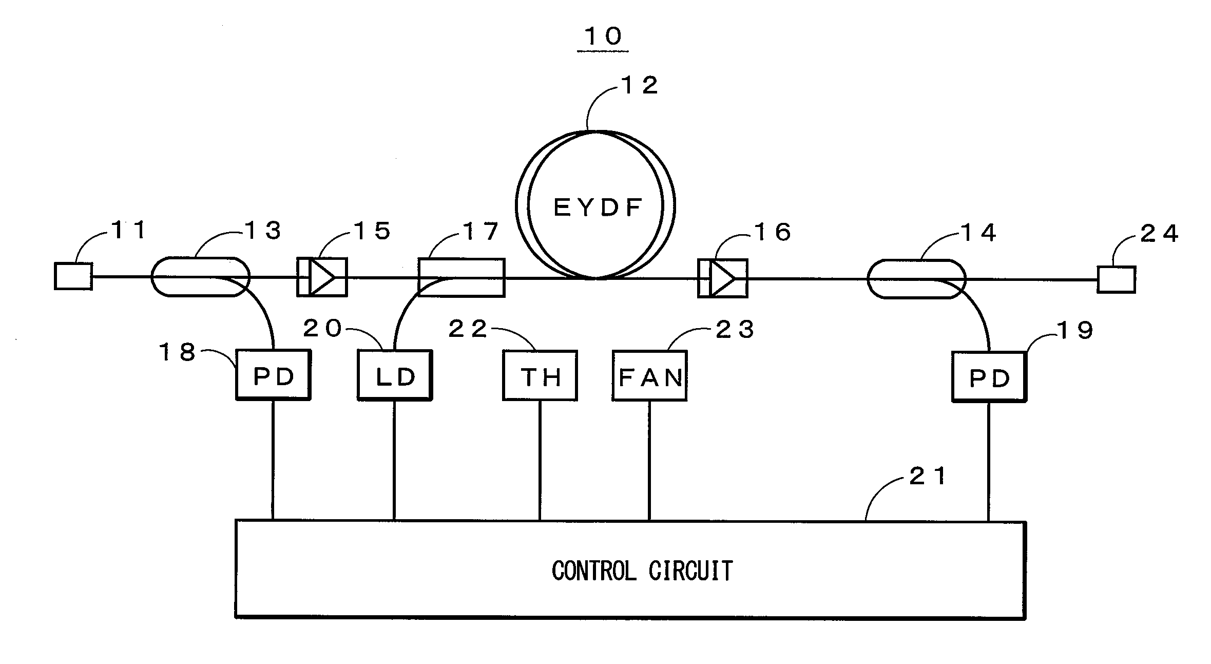
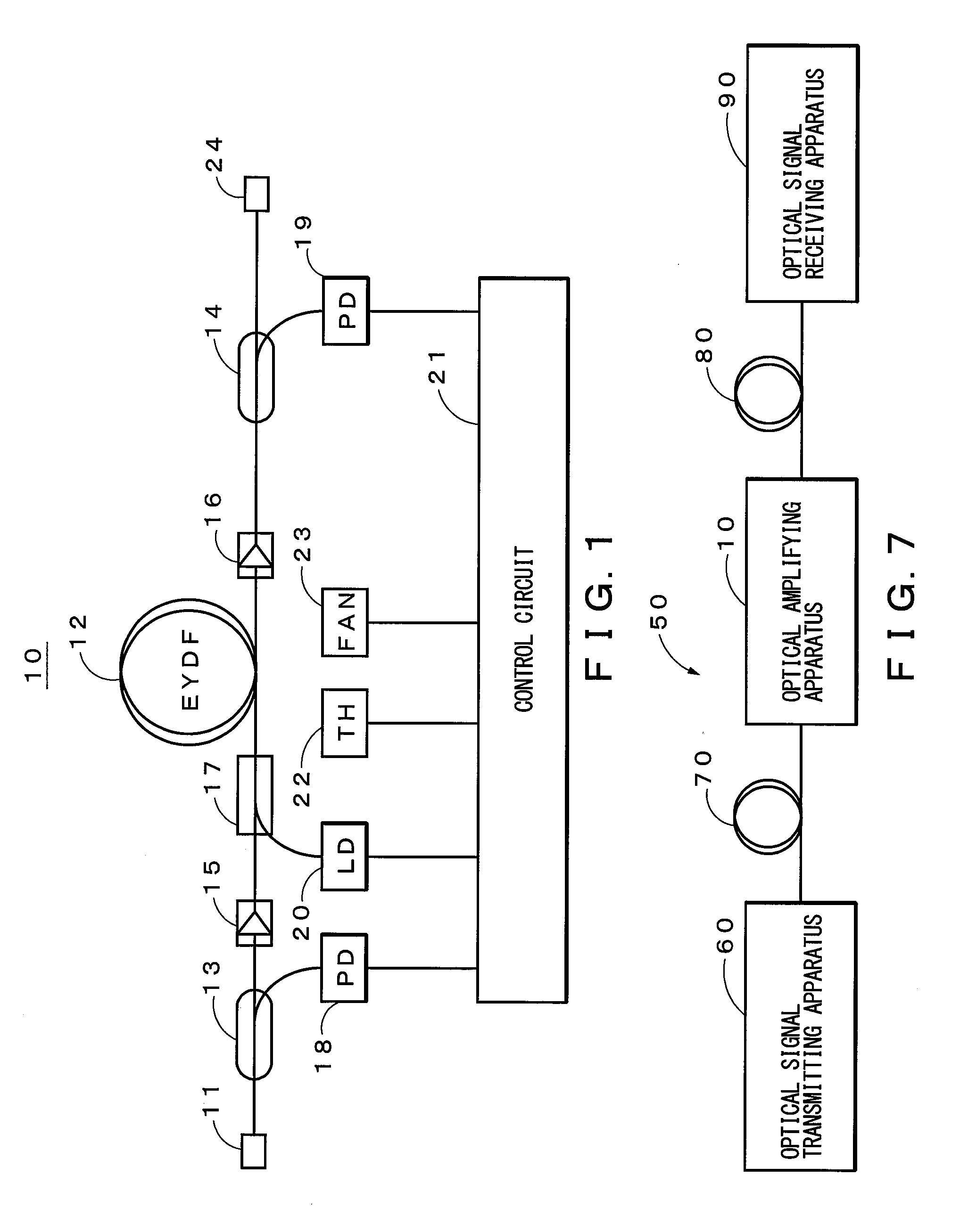
[0033]FIG. 1 is a diagram showing an exemplary configuration of an optical amplifying apparatus of an embodiment of the invention. As shown in FIG. 1, an optical amplifying apparatus 10 includes an input port 11, an amplification optical fiber 12, optical couplers 13 and 14, optical isolators 15 and 16, a pump light mixer 17, photodiodes 18 and 19, a laser diode 20, a control circuit 21, a thermistor 22, a cooling section 23 and an output port 24.

[0034]The input port 11 is, for example, an optical connector or the like, and for example, an optical signal having a wavelength of 1550 nm obtained by modulating laser light with a AM-VSB (Amplitude Modulation-Vestigial Side-Band) signal having 40 sinusoidal carriers within a frequency range of 91.25-343.25 MHz is inputted thereto. The amplification optical fiber (EYDF: Erbium Ytterbium Doped Fiber) 12 amplifies the optical signal by a ...


PUM


Abstract

An optical amplifying apparatus that amplifies an optical signal, including an input section whereto the optical signal is inputted, a laser light source that generates laser light, the laser light source including an uncooled semiconductor laser device, an optical fiber that amplifies the optical signal by a stimulated emission based on the laser light from the laser light source, an output section that outputs the optical signal amplified by the optical fiber, and a passive optical component disposed between the optical fiber and the output section. The laser light source is thermally coupled to the optical fiber and/or the passive optical component via a thermally conductive medium. An oscillating wavelength of the laser light source is varied by increasing a temperature of the laser light source with heat generated by the optical fiber and/or the passive optical component.

Description

CROSS REFERENCE TO RELATED APPLICATIONS[0001]This is a continuation application of International Patent Application No. PCT / JP2010 / 069324, filed Oct. 29, 2010, the full content of which is hereby incorporated by reference herein in its entirety.TECHNICAL FIELD[0002]The present invention relates to an optical amplifying apparatus and an optical transmission system that are applicable in the field of optical communication or the like.BACKGROUND ART[0003]Recently, fiber optic communication networks called FTTx (Fiber To The x) such as a fiber optic communication network reaching a user's home are widespread. In such a fiber optic communication network, an optical amplifying apparatus is used for the purpose of compensating for transmission losses in a transmission path and distribution losses in a distributor for that distributes optical signals between a plurality of subscribers.[0004]Such an optical amplifying apparatus may be, for example, a known fiber-type optical amplifying appar...

Claims


Application Information

Patent Timeline
Patent Type & Authority Applications(United States)
IPC IPC(8): H01S5/06H01S3/13H01S3/067
CPCH01S3/0405H01S3/06704H01S3/06754H01S3/094007H01S3/09415H01S3/10015H01S5/0612H01S3/1608H01S3/1618H01S5/02252H01S5/02453H01S3/13H01S3/1301H01S3/13013H01S5/02326
Inventor SUZUKI, MIKIYA
Owner FURUKAWA ELECTRIC CO LTD
Why Eureka
Try Eureka