
Pyrolyzer furnace apparatus and method for operation thereof

a technology of pyrolysis furnace and furnace, which is applied in the direction of lighting and heating apparatus, combustion types, inclined chamber coke ovens, etc., can solve the problems of shortened life of furnace components, increased fuel consumption of pyrolysis furnace, and energy efficiency of previous pyrolysis furnaces

Inactive Publication Date: 2013-09-19
NUCOR CORP
View PDF0 Cites 35 Cited by
  • Summary
  • Abstract
  • Description
  • Claims
  • Application Information

AI Technical Summary

Benefits of technology

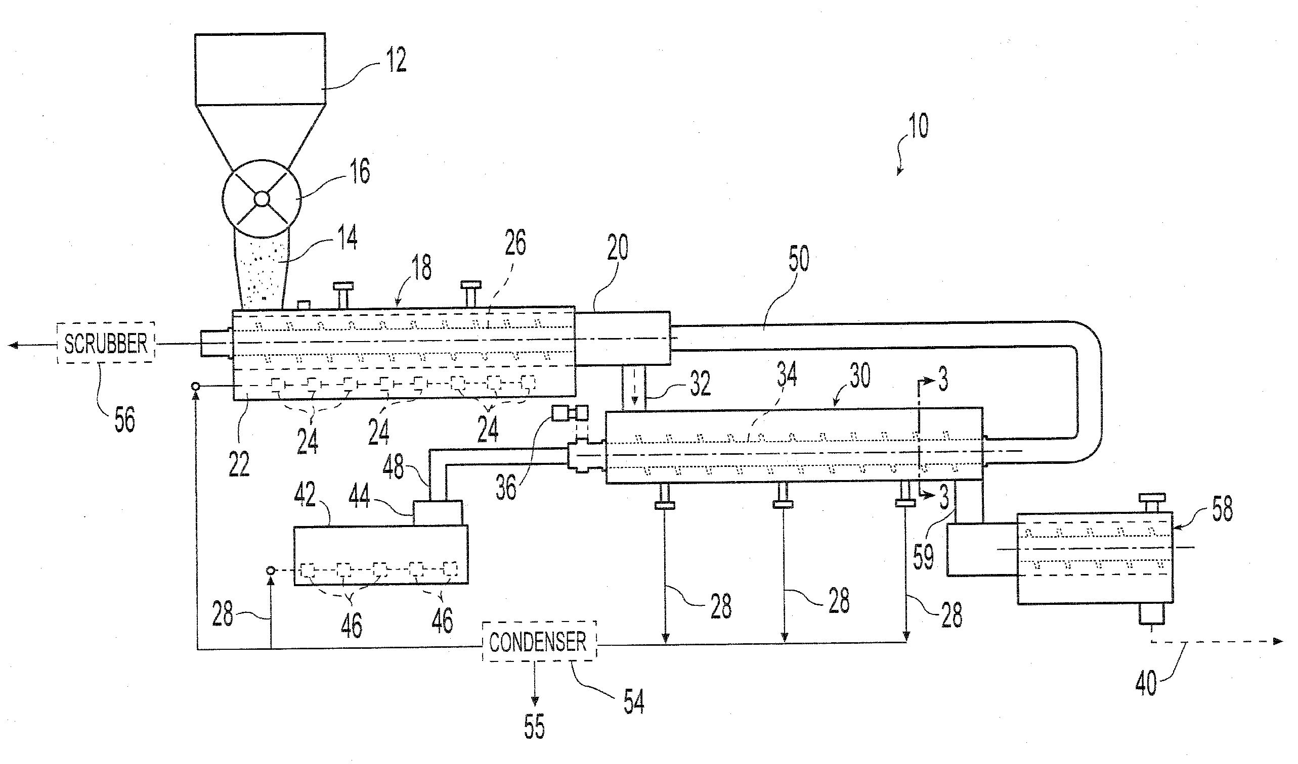
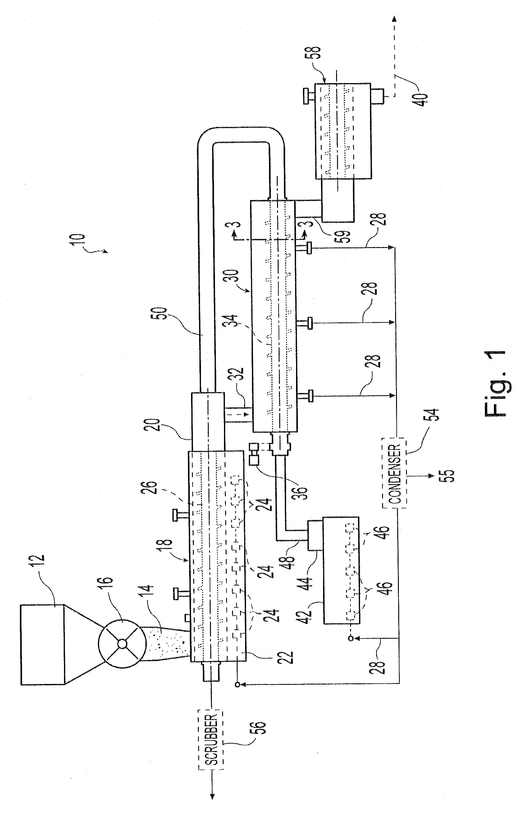
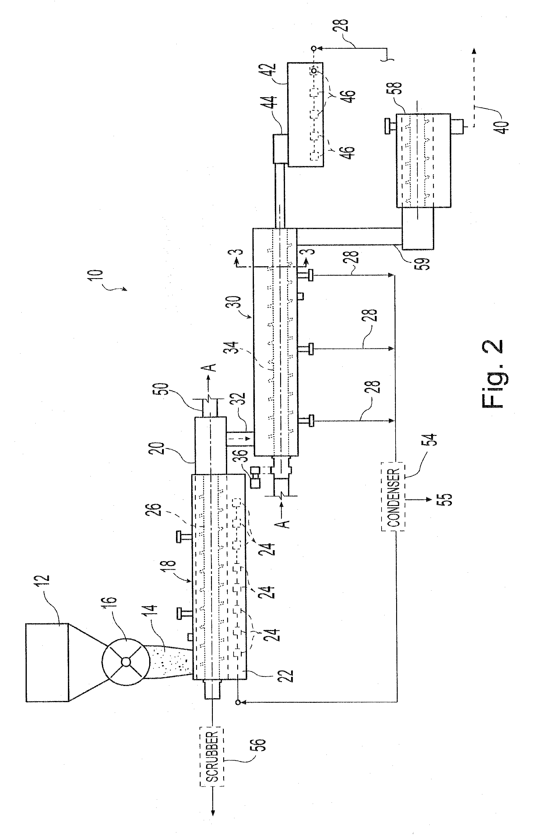
This patent describes a new system for making char, which reduces the amount of energy needed. The system uses a pyrolyzer furnace and a method to make char more efficiently. With this system, char can be made using only the heat from the process of making char, eliminating the need for additional energy. The system also includes devices that create high-speed fluid flow and a tapered shaft to compact the char before it exits the furnace.

Problems solved by technology

Previous pyrolyzer furnaces disclosed by the prior art had heating elements positioned within the furnace housing, which generated hot spots within the furnace, caused uneven heating of the coal or other coal-bearing material, and caused fatigue and shortened the life of the furnace components.
Another limitation has been the energy efficiency of previous pyrolyzer furnaces.
Pyrolyzer furnaces in the prior art also had drive screws with solid shafts, oil cooled shafts, and other shaft configurations that were thermally inefficient, resulting in the pyrolyzer furnace consuming more fuel.

Method used


Image

  • Pyrolyzer furnace apparatus and method for operation thereof
  • Pyrolyzer furnace apparatus and method for operation thereof
  • Pyrolyzer furnace apparatus and method for operation thereof

Examples


examples

[0143]In various tests of the pyrolyzer and briquetting processes, char was produced in a twin-screw pyrolyzer and briquetted with a binding coal and binding agent and briquetted. The briquettes were carbonized and the strength (CSR) and reactivity (CRI) of the formed coke briquettes were measured according to a modified ASTM D5341-99 standard using uncrushed briquettes.

[0144]The char may be formed in the twin-screw pyrolyzer as described above from two different sources of coal-bearing material: Teco Myra coal (described in Appendix A) and Solar Sources coal (described in Appendix B). Each of these coals may be mixed with one of two different binder coals: Virginia Crews (described in Appendix C) and Blue Creek 7 (described in Appendix D). A binding agent, asphalt Shell HV06, was then added to the mixture and the resultant blend was briquetted at 560 to 600 bar in briquetting rolls. Each of the blends comprised 60% char, 30% binder coal, and 10% binding agent.

[0145]In order to test...


PUM


Abstract

A char making apparatus comprises a longitudinal pyrolyzer furnace housing wherein coal-bearing material may be heated to a temperature to fluidize volatile materials therein and plasticize coal in the coal-bearing material. At least two rotatable drive screws are laterally positioned and interleaved within the longitudinal furnace housing and capable of conveying coal-bearing materials through the pyrolyzer furnace housing, each drive screw having a hollow drive shaft and a diverter positioned within the drive shaft to provide heating to the coal-bearing material. A heating jacket about the longitudinal furnace housing provides additional heating to the coal-bearing material. Multiple combustion chambers adjacent the heating jacket and hollow drive shaft burn fluidized volatile materials and exhaust combustion fluids through the jacket and shaft.

Description

[0001]This application is a continuation-in-part of application Ser. No. 11 / 959,581, filed Dec. 19, 2007, which claims the benefit of U.S. Provisional Patent Application 60 / 871,863 filed Dec. 26, 2006, incorporated herein by reference in its entirety.BACKGROUND AND SUMMARY OF THE DISCLOSURE[0002]The present invention relates to processing methods and apparatus for converting coal or other coal-bearing materials into char. Char can be produced by heating coal or other coal-bearing materials to selected temperatures in a reduced-oxygen environment. Char having suitable properties may be used in, among other things, iron and steel processing furnaces.[0003]Heating coal or other coal-bearing materials in a reduced-oxygen environment produces coal gas, volatile liquids and a residue of char. During the process of making char, volatile materials, such as hydrocarbon fuels, in the coal-bearing materials fluidize when heated to a temperature of approximately 650° F. (approximately 350° C.) ...

Claims


Application Information

Patent Timeline
IPC IPC(8): C10B49/10
CPCC10J3/007C10B47/44F23G5/0273C10J2300/0909C10J2300/093C10J2300/0973C10J2200/156C10J2300/1223C10J2300/1246C10B49/10F23G2201/303F23G2203/8013C10J2300/1207B30B11/00C10B1/06C10B7/10C10B21/00C10B45/02C10B47/24C10B57/04C10L5/12C10L5/22C10L2290/02C10L2290/24C10L2290/28C10B1/08C10B11/00C10B37/04C10L5/04C10L5/08C10L2290/30
Inventor WOLFE, RICHARD A.
Owner NUCOR CORP
Learn More