Load Distribution System and Power Management System and Method

a load distribution and load technology, applied in the field of power supplies, can solve the problems of inability to adapt or scale to various deployment scenarios, limited power available from the power source, and usually wasted capacity, and achieve the effect of precise power control and easy adaptability

Inactive Publication Date: 2013-09-19
TRANSISTOR DEVICES
View PDF13 Cites 22 Cited by
  • Summary
  • Abstract
  • Description
  • Claims
  • Application Information

AI Technical Summary

Benefits of technology

[0012]The power management system of the invention allows precise power control and easy adaptability for distributed power management from a power source to multiple users served by a plurality of power units, where there are limitations on the amount of power available to the p

Problems solved by technology

The available power from the power source is limited by the total output of the generator(s) or APU or inverter, and by demands on the power source by the aircraft's own systems.
This “buffer” power is usually wasted capacity, since a typical user may only need half that amount or less.
To date, these methods are either administered from a central power distribution unit (PDU), or are set up in such a way that they are not easily adaptable or scalable to various deployment scenarios.
Legacy systems often emp

Method used


Image

  • Load Distribution System and Power Management System and Method
  • Load Distribution System and Power Management System and Method
  • Load Distribution System and Power Management System and Method

Examples


embodiment 1

DC Current Monitor Bus Control

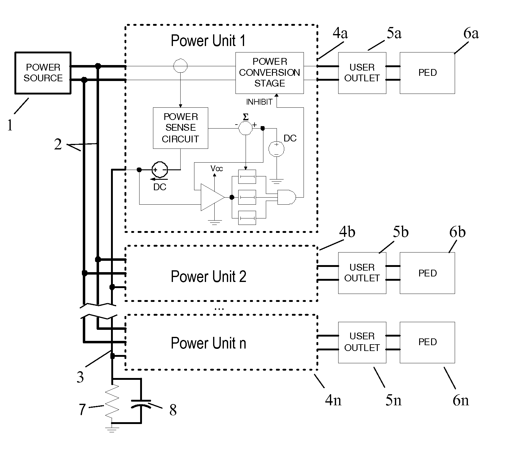
[0030]In this embodiment, each power unit 4a-4n adds a current to this monitor bus 3 proportional to the current it is drawing from the power bus 2. In this embodiment the monitor bus 3 is grounded through a reference resistor 7 at one point. This point could be at one end of the branch, or in a master control unit which supplies the power to the branch, or in one of the power units 4a-4n, or anywhere else on the branch as desired. The reference resistor 7 thus serves as a simple, system level threshold determination device. As current is added to the monitor bus 3 by the power units 4a-4n, a voltage drop is generated by the reference resistor 7 which is proportional to the total current being drawn from power bus 2 by all of the power units 4a-4n. If desired for noise decoupling, a capacitor 8 can be provided in parallel with resistor 7 as shown in FIG. 1.

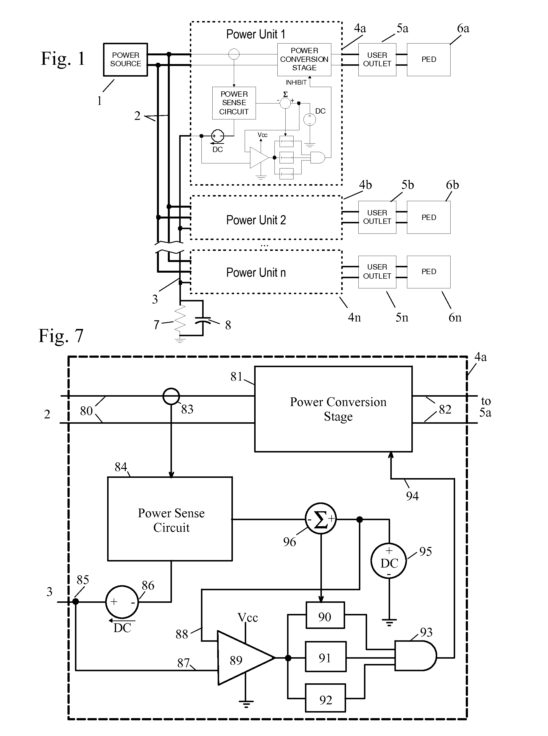
[0031]FIG. 7 shows a detail of a representative single power unit 4a from FIG. 1. It should be not...

embodiment 2

Pulse Rate Monitor Bus Control

[0061]Referring to FIGS. 8 and 9, the basic system of this embodiment is the same as described for the first embodiment, and the common elements will not be separately described here.

[0062]FIG. 9 shows a detail of a representative single power unit 4a from FIG. 8. As with the first embodiment, the power unit 4a has a power conversion stage 81, which takes electrical power on its input 80 which is connected to power bus 2 (say 115VAC at 400 Hz), and converts it to a different voltage and / or frequency (say, 120VAC 60 Hz) at an output 82 which connects to outlet 5a. The power conversion stage 81 can be shut off by a signal on INHIBIT line 94.

[0063]The current in the power conversion stage 81 is measured by a sensor 83, which is input to power sense circuit 84. The example shows sensor 83 sensing current in the input 80 to power conversion stage 81, so that the sensor 83 directly reads current drawn from the power bus 2. It will be understood that the curre...

embodiment 3

Control by Digital Signals on Digital Monitor Bus

[0079]In another possible implementation, the analog share bus is implemented digitally by any one of a number of common communications buses, such as CAN bus or Ethernet. Each unit would report its load current, and each unit could then know all the currents. Any type of algorithm could be implemented to drop of users for load shedding. The first user to be dropped could be the user who has been on the longest time, the user who has consumed the least watt-hours, the user who has consumed the most watt-hours, etc.

Tri-State Signal Interface

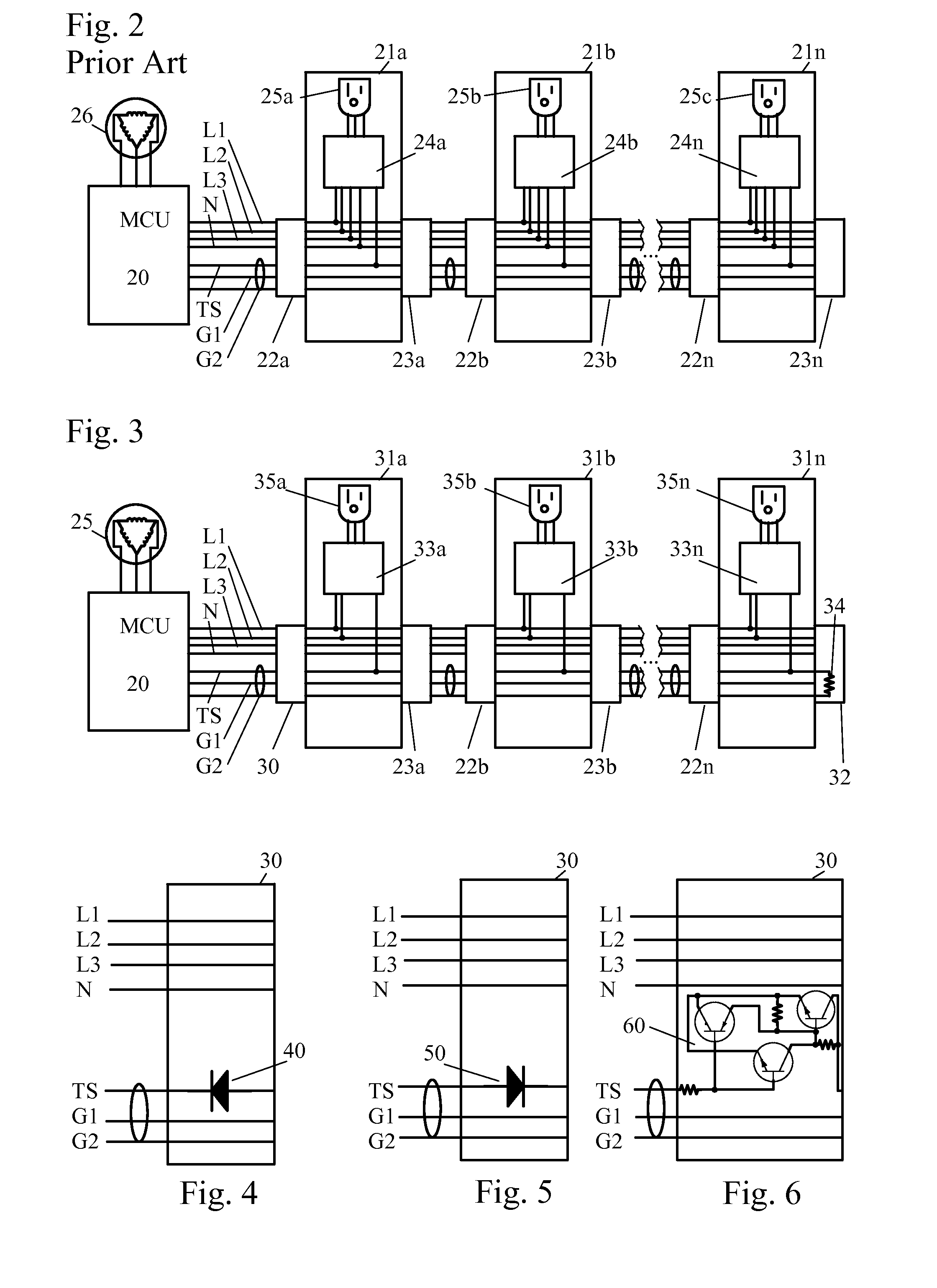
[0080]Legacy aircraft cabin power systems employ a centrally generated tri-state signal that is daisy chained between units. FIG. 2 shows a system of the prior art in such an arrangement. The legacy system has takes three-phase 400 Hz AC power from the aircraft generator 26, and routes the power from generator 26 through a Master Control Unit (MCU) 20 to a three-phase power bus with lines L1-L3 and ...


PUM


Abstract

A power management system for distributed power management from a power source to a plurality of power units, using a monitor bus to monitor total power usage on a branch to which the power unit is assigned, allowing power to be delivered if it won't result in a maximum current draw from the power source being exceeded, and denying access if it would. Each power unit adds a signal to the monitor bus proportional to the current it is drawing from the power source.

Description

REFERENCE TO RELATED APPLICATIONS[0001]This application claims one or more inventions which were disclosed in the following U.S. Provisional Applications: No. 61 / 610,775, filed Mar. 14, 2012, entitled “Load Distribution System and Power Management System and Method”; No. 61 / 611,204, filed Mar. 15, 2012, entitled “Power Management System using Power Supplies Adapted To Use Tri-State Power Management Signals”; No. 61 / 611,713, filed Mar. 16, 2012, entitled “Load Distribution System and Power Management System and Method”; and No. 61 / 616,078, filed Mar. 27, 2012, entitled, “Power Management System using Power Supplies Adapted To Use Tri-State Power Management Signals”. The benefit under 35 USC §119(e) of the United States provisional application is hereby claimed, and the aforementioned application is hereby incorporated herein by reference.BACKGROUND OF THE INVENTION[0002]1. Field of the Invention[0003]The invention pertains to the field of power supplies. More particularly, the invent...

Claims


Application Information

Patent Timeline
IPC IPC(8): H02J4/00
CPCH02J4/00H02J2003/143H02J3/14Y02B70/3225Y04S20/222Y04S20/242H02J2310/14H02J13/00002H02J13/00004Y02B70/30H02J2310/60Y04S10/30Y02E60/00
Inventor SANTINI, JOHNROZENBLAT, LAZARDELUCA, RONALDMULCAHY, GARY
Owner TRANSISTOR DEVICES
Why Eureka
Try Eureka