Doubly-Fed Generator and Doubly-Fed Electric Machine
- Summary
- Abstract
- Description
- Claims
- Application Information
AI Technical Summary
Benefits of technology
Problems solved by technology
Method used
Image
Examples
embodiment 1
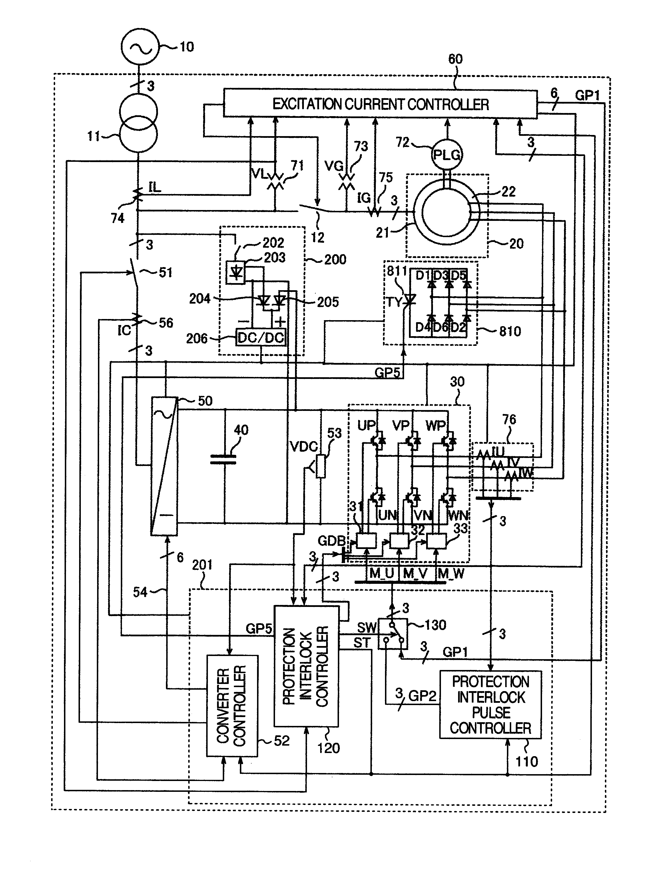
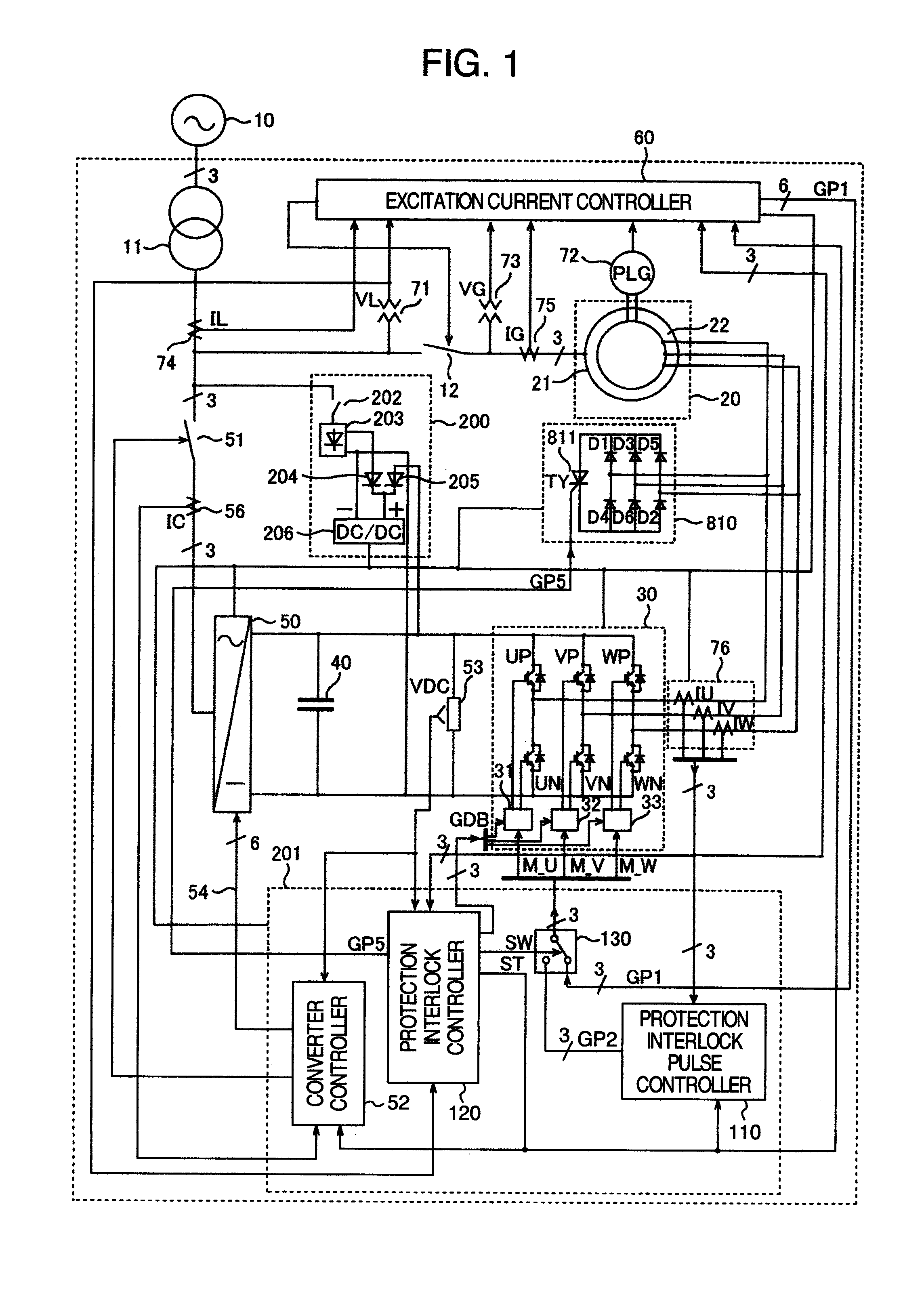
[0040]The configuration of embodiment 1 according to this invention will be explained by referring to FIG. 1.
[0041]In this embodiment, as a doubly-fed generator, a doubly-fed electric machine commonly used in a wind power generation system is employed, with a stator side armature winding 21 of a wound-rotor induction machine connected to a power grid 10 through a transformer 11 and a circuit breaker 12.
[0042]A first power converter 30 has six three-phase bridge connected arms (UP, VP, WP, UN, VN, WN), each made up of anti-parallelly connected self-turn-off power device and diode, and is controlled to turn on and off by pulse width modulation commands (M_U, M_V, M_W). A capacitor 40 is connected between DC side terminals of the first power converter 30. The internal configuration of the first power converter 30 will be described later referring to FIG. 10.
[0043]A second power converter 50 has its DC side terminals connected to both ends of the capacitor 40 and its AC side terminals c...
embodiment 2
[0079]FIG. 6 shows a second embodiment of this invention.
[0080]A resistor 310 and a self-turn-off device 320 (CHV) form a circuit to minimize a voltage increase in the DC circuit. When the DC voltage VDC exceeds a preset value VD1, a firing command GP3 from a protection interlock controller 140 is turned on to lower the voltage. When the DC voltage goes below a preset value VD2, the GP3 is turned off. This arrangement allows the operation to continue even when the energy, which is triggered by GP2 to flow in from the rotor circuit 22 of the wound-rotor induction machine, fails to be released to the grid side by the control of the second power converter, resulting in a voltage increase.
[0081]A non-linear resistor 410 using a zinc oxide device is able to suppress a voltage increase in a DC circuit and may be used in place of the resistor 310 and the self-turn-off device 320 (CHV) or in combination.
[0082]FIG. 6 represents an example in which the non-linear resistor 410 is connected wit...
PUM
 Abstract
Description
Claims
Application Information
 - R&D
- Intellectual Property
- Life Sciences
- Materials
- Tech Scout
- Unparalleled Data Quality
- Higher Quality Content
- 60% Fewer Hallucinations
Browse by: Latest US Patents, China's latest patents, Technical Efficacy Thesaurus, Application Domain, Technology Topic, Popular Technical Reports.
© 2025 PatSnap. All rights reserved.Legal|Privacy policy|Modern Slavery Act Transparency Statement|Sitemap|About US| Contact US: help@patsnap.com


