Method for manufacturing common mode filter and common mode filter

Inactive Publication Date: 2013-09-19
SAMSUNG ELECTRO MECHANICS CO LTD
View PDF6 Cites 11 Cited by
  • Summary
  • Abstract
  • Description
  • Claims
  • Application Information

AI Technical Summary

Benefits of technology

[0013]An object of the present invention is to provide a method for manufacturing common mode filter and a common mode filter that are ca

Problems solved by technology

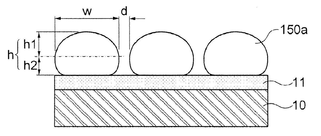
However, since there is a limitation in decreasing the spaced distance d between the adjacent coils due to the limitation in the photo-resist process des

Method used


Image

  • Method for manufacturing common mode filter and common mode filter
  • Method for manufacturing common mode filter and common mode filter
  • Method for manufacturing common mode filter and common mode filter

Examples


Embodiment Construction

[0037]Various advantages and features of the present invention and methods accomplishing thereof will become apparent from the following description of embodiments with reference to the accompanying drawings. However, the present invention may be modified in many different forms and it should not be limited to the embodiments set forth herein. These embodiments may be provided so that this disclosure will be thorough and complete, and will fully convey the scope of the invention to those skilled in the art. Like reference numerals throughout the description denote like elements.

[0038]Terms used in the present specification are for explaining the embodiments rather than limiting the present invention. Unless explicitly described to the contrary, a singular form includes a plural form in the present specification. The word “comprise” and variations such as “comprises” or “comprising,” will be understood to imply the inclusion of stated constituents, steps, operations and / or elements b...


PUM


Abstract

Disclosed herein are a method for manufacturing common mode filter and a common mode filter. The method includes: performing electroplating on first coil patterns made of a conductive material to form second coil patterns having a cross-sectional area increased as compared to the first coil patterns. Therefore, the common mode filter fulfilling a miniaturization demand and having the improved characteristics such as the inductance, the DC resistance, and the like, may be implemented.

Description

CROSS REFERENCE(S) TO RELATED APPLICATIONS[0001]This application claims the benefit under 35 U.S.C. Section 119 of Korean Patent Application Serial No. 10-2012-0026674, entitled “Method for Manufacturing Common Mode Filter and Common Mode Filter” filed on Mar. 15, 2012, which is hereby incorporated by reference in its entirety into this application.BACKGROUND OF THE INVENTION[0002]1. Technical Field[0003]The present invention relates to a method for manufacturing common mode filter and a common mode filter.[0004]2. Description of the Related Art[0005]A common mode filter (CMF) is an electronic component widely used in various electronic devices in order to remove common mode noise.[0006]Recently, in accordance with miniaturization, slimness, and multi-functionalization of electronic products, research into a CMF capable of improving noise removing performance and being miniaturized and thinned has been continuously conducted.[0007]In addition, various researches and attempts have be...

Claims


Application Information

Patent Timeline
IPC IPC(8): H01F5/00H01F41/04
CPCH01F17/0013H01F41/042H01F5/003H01P1/20
Inventor YANG, JU HWANSIM, WON CHULYOO, YOUNG SEUCKWI, SUNG KWON
Owner SAMSUNG ELECTRO MECHANICS CO LTD
Why Eureka
Try Eureka