Automatically Determining 3D Catheter Location and Orientation Using 2D Fluoroscopy Only

a fluoroscopy and location technology, applied in the field of medical imaging systems, can solve the problems of limited usefulness, inconvenient operation, and high cost of conventional fluoroscopy systems, and achieve the effect of z-coordinate accuracy

Active Publication Date: 2013-09-19
APN HEALTH
View PDF3 Cites 67 Cited by
  • Summary
  • Abstract
  • Description
  • Claims
  • Application Information

AI Technical Summary

Benefits of technology

[0018]Yet another object of the present invention is to provide a medical imaging system which improves the accuracy and therefore the effectiveness of medical procedures by using gated images to minimize the effect of motion during operation.
[0020]Still another object of the present invention is to provide such a system with sub-pixel image measurement accuracy, thereby achieving useful z-coordinate accuracy at a economical level not available with other systems.
[0054]In particular preferred embodiments, the steps of capturing, detecting, applying geometric calculations, applying corrections, and calculating 3D position and orientation are performed multiple times with the medical object in a single position and the calculated 3D position and orientation data is averaged for the purpose of enhancing accuracy of the determination of 3D position and orientation.

Problems solved by technology

These systems are, however, quite expensive to both acquire and operate.
Therefore, these systems are available only in a few laboratories for use during interventional procedures, and some of these systems may require specifically-designed catheters such as catheters with built-in sensors.
As illustrated in FIGS. 1A and 1B, fluoroscopy images produced by conventional systems have the limitation that they do not provide 3D image data.
However, its usefulness is limited due to cost and to excessive radiation, and only 1 to 2% of interventional labs have the capability to perform biplane fluoroscopy.
However, in some scenarios, the restrictions on catheter advancement are too severe to be able to reduce 3D position errors.

Method used


Image

  • Automatically Determining 3D Catheter Location and Orientation Using 2D Fluoroscopy Only
  • Automatically Determining 3D Catheter Location and Orientation Using 2D Fluoroscopy Only
  • Automatically Determining 3D Catheter Location and Orientation Using 2D Fluoroscopy Only

Examples


embodiment 20

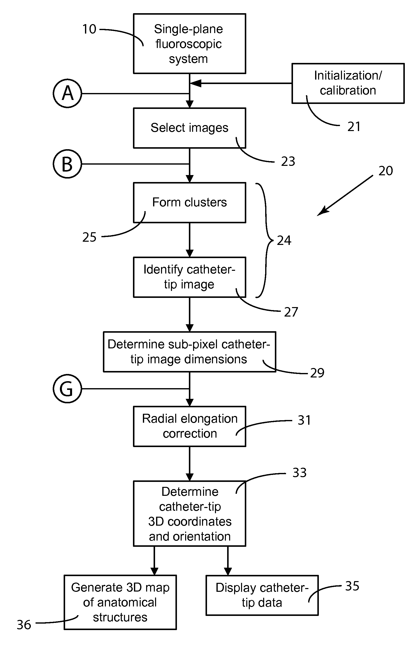
[0090]FIG. 4 is a general schematic of the inventive method for determining the 3D location of an object such as catheter using a single-plane fluoroscopic system. For convenience, the inventive system henceforth is called the Catheter Tip 3D Location System and will be referred to herein as C3DLS to shorten the terminology. The term “system” to describe the method since the method is carried out primarily by software which constitutes a system in the wider use of the term. The terms “process” and “functional element” as well as the specific terms referred to in the various elements in the schematic figures are used interchangeably herein in describing the operations or method steps of the inventive method or system.

[0091]C3DLS 20 includes the use of a conventional single-plane fluoroscopic system 10 which generates a series of sequential 2D fluoroscopic images which are available as a stream of digital images. The rate at which such images are generated may be a typical rate such a...

second embodiment

[0159]FIG. 15A illustrates a composite R-wave detector, composite R-wave detection system 50c2. Composite R-wave detection system 50c2 includes similar inputs as composite R-wave detection system 50c1 and the same channel R-wave detection systems to generate channel trigger signal t1(t)-tn(t). Channel R-wave trigger signals t1(t)-tn(t) are inputs to a trigger-window filter 100. Trigger-window filter 100 outputs a composite R-wave trigger in a trigger output tc(t) (101). Trigger-window filter 100 is configured to output a trigger in trigger output tc(t) when it receives a channel R-wave trigger from any one of the channel R-wave detectors. When such a trigger occurs in tc(t), all channel trigger signals from the channel R-wave detectors not triggering composite R-wave detector 50c2 are ignored for a predetermined time period (lockout period tLO) after composite R-wave detector trigger output tc(t) is triggered.

[0160]FIG. 15B illustrates one such triggering. Channel R-wave trigger sig...


PUM


Abstract

A method for automatically determining the 3D position and orientation of a radio-opaque medical object in a living body using single-plane fluoroscopy comprising capturing a stream of digitized 2D images from a single-plane fluoroscope (10), detecting the image of the medical object in a subset of the digital 2D images, applying pixel-level geometric calculations to measure the medical-object image, applying conical projection and radial elongation corrections (31) to the image measurements, and calculating the 3D position and orientation of the medical object from the corrected 2D image measurements.

Description

RELATED APPLICATIONS[0001]This application claims the benefit of U.S. Provisional Applications 61 / 573,557, filed on Sep. 8, 2011, and 61 / 627,728, filed on Oct. 17, 2011, the entire contents of which are incorporated herein by reference.FIELD OF THE INVENTION[0002]The present invention generally relates to medical imaging systems and more particularly to 2D fluoroscopic systems for use during interventional medical procedures.BACKGROUND OF THE INVENTION[0003]Anatomical mapping systems provide the 3D position of a navigational catheter within the cardiac chamber of interest and, in some instances, can also be used to construct 3D maps of the cardiac chamber. These systems are, however, quite expensive to both acquire and operate. Therefore, these systems are available only in a few laboratories for use during interventional procedures, and some of these systems may require specifically-designed catheters such as catheters with built-in sensors.[0004]Conventional fluoroscopy systems ar...

Claims


Application Information

Patent Timeline
Patent Type & Authority Applications(United States)
IPC IPC(8): A61B6/00A61B6/02A61B5/352
CPCA61B6/022A61B6/485A61B5/0456A61B6/12A61B6/4441A61B6/463A61B5/7289A61B6/503A61B6/5288A61B2019/5295A61B6/5264A61B6/582A61B6/487A61B2090/367A61B5/352A61B2090/376A61B2034/2065A61B5/061
Inventor SRA, JASBIRBELANGER, BARRYPAULMA, MARKBRODNICK, DONALDLANGENBACH, BRUCEJANSSON, DAVID G.
Owner APN HEALTH
Why Eureka
Try Eureka