Heating system and method for controlling a heating system

Active Publication Date: 2013-09-26
DAIKIN IND LTD +1
View PDF29 Cites 23 Cited by
  • Summary
  • Abstract
  • Description
  • Claims
  • Application Information

AI Technical Summary

Benefits of technology

[0008]In view of the above, it is an object of the present invention to provide a hybrid heating system and a method for controlling such a heating system

Problems solved by technology

A disadvantage of such system is that the heat pump and the conventional heating system are alternatively operated.
A disadvantage of such a system is that the heat pump i

Method used


Image

  • Heating system and method for controlling a heating system
  • Heating system and method for controlling a heating system
  • Heating system and method for controlling a heating system

Examples


Embodiment Construction

[0040]Reference numerals used throughout the drawings have been used consistently representing the same or similar parts of the heating system. If one element is described with respect to one embodiment, the description of the same element is omitted in the other embodiment / -s and reference is made to the previous description in regard of the embodiment / -s.

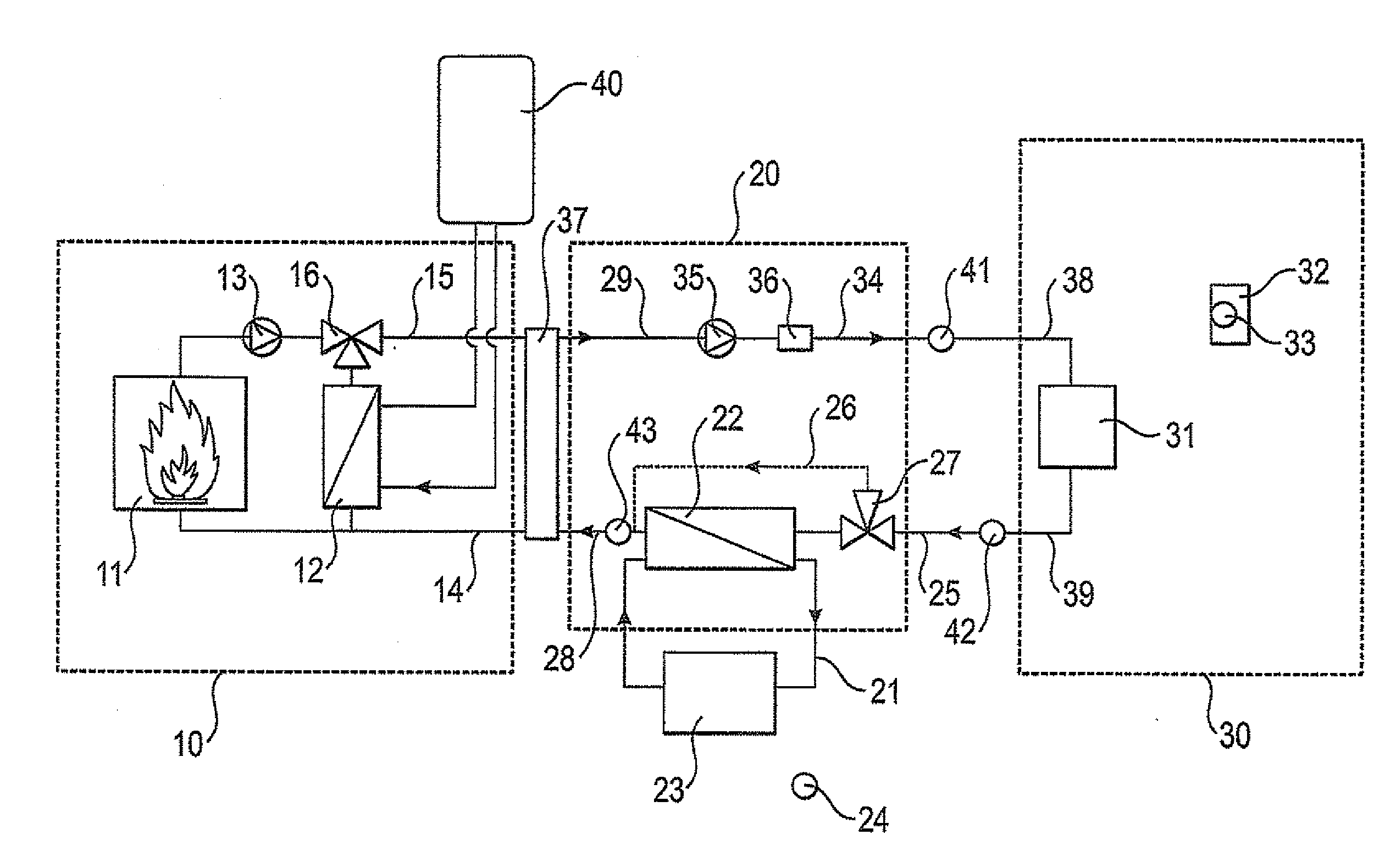
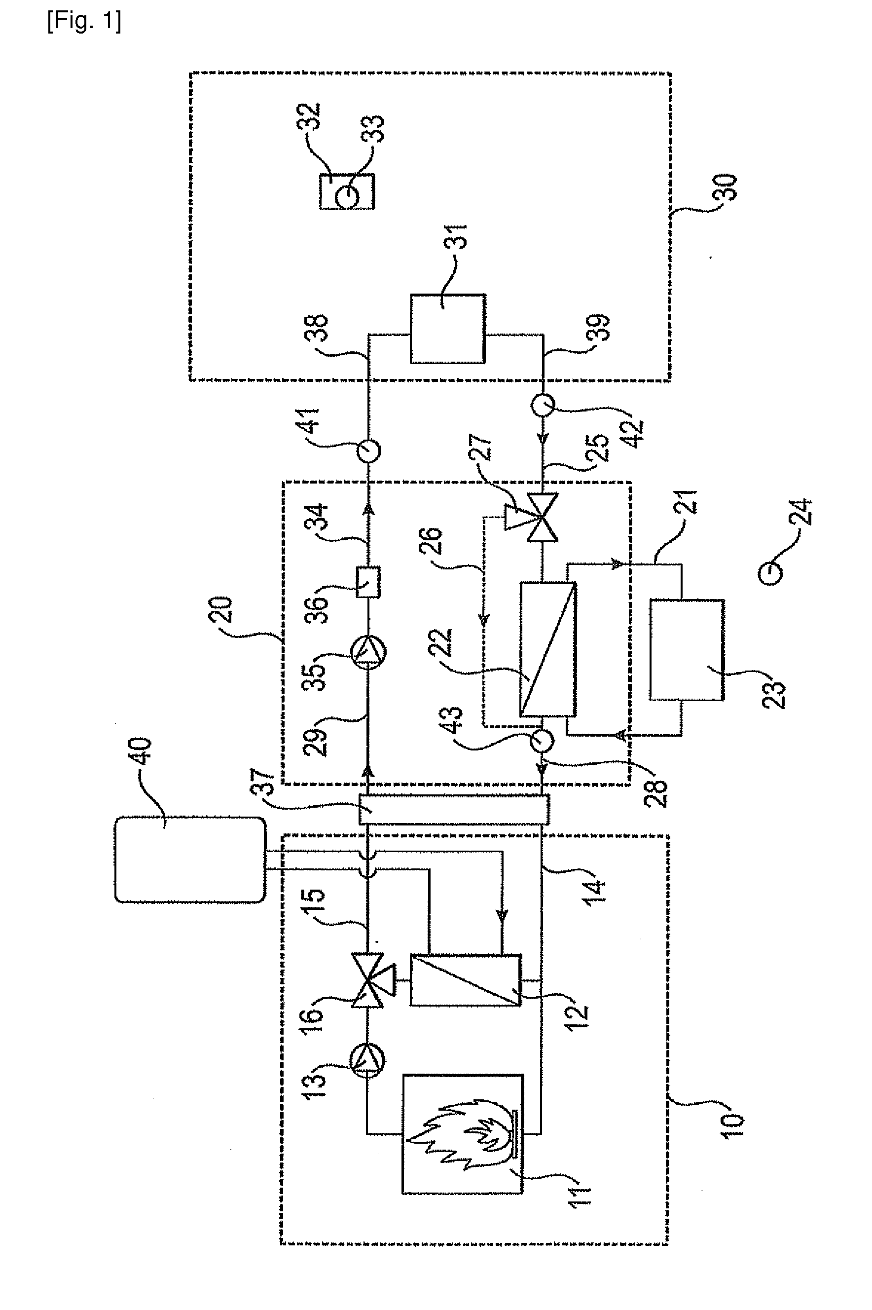
[0041]FIG. 1 shows a schematic diagram of a heating system according to an embodiment of the invention. The heating system comprises a boiler unit 10, a heat pump unit 20 and an emitting section 30.

[0042]The emitting section 30 will in most cases and if the heating system is used for residential heating comprise a plurality of heat emitters such as radiators, floor heating and / or convectors which are located in a plurality of rooms representing the space to he heated. In Figure 1 the heat emitters have been schematically referred to by the reference numeral 31. Further comprised within the space to be heated is one or more thermos...


PUM


Abstract

A heating system includes a flow circuit carrying working fluid at a set flow temperature to a heat emitting section, an electricity driven heat pump having a first heat exchanger, and a fuel fired boiler having a second heat exchanger. The first and second heat exchangers arc connected to the flow circuit to heat the working fluid in succession. A coefficient of performance (COPSet Flow Temperature) of the heat pump and a break even coefficient of performance (BECOP) are determined, and the COPSet Flow Temperature and BECOP compared. The BECOP is electricity price/fuel price*boiler thermal efficiency. If the COPSet Flow temperature is smaller than the BECOP in a first hybrid mode, an intermediate flow temperature is determined, the heat pump is operated to heat the working fluid to the intermediate flow temperature and the boiler is operated to heat the working fluid to the set flow temperature.

Description

CROSS-REFERENCE TO RELATED APPLICATIONS[0001]This U.S. National stage application claims priority under 35 U.S.C. §119(a) to European Patent Application No. 10194129.2, filed in Europe on Dec. 8, 2010, the entire contents of which are hereby incorporated herein by reference.BACKGROUND[0002]1. Technical Field[0003]The present invention relates to a heating system for space heating and a method for controlling such a heating system. In particular, the present invention relates to a so called hybrid heating system having an electricity-driven heat pump as a first heat source and a fuel fired boiler as a second heat source for heating a working fluid.[0004]2. Background Art[0005]Such a hybrid heating system is for example known from WO-A-2010 / 058397 A1. This system is configured to operate the heat pump when the operation of the heat pump is less expensive than the operation of the conventional heating system, such as a fuel fired boiler, and to operate the conventional heating system w...

Claims


Application Information

Patent Timeline
IPC IPC(8): F24D12/02F24D19/10F24D15/04
CPCF24D3/08F24D19/1072F24D2200/046F24D2200/123Y02B30/14Y02B30/12F24D2220/0228F24D12/02F24D15/04F24D19/1039F24D3/18Y02B30/00F24H15/258F24H15/36F24H15/281F24H15/335F24H15/277F24H15/254F24H15/375F24H15/164
Inventor ASPESLAGH, BARTDEBAETS, STEFANIE
Owner DAIKIN IND LTD
Why Eureka
Try Eureka