System and method for constructing modular concrete ducts

a concrete duct and modular technology, applied in the field of concrete duct structures, can solve the problems of duct connection leakage, duct cracking, gasket not being properly compressed, etc., and achieve the effect of tight machining tolerances and extended size rang

Active Publication Date: 2013-09-26
SOUTHERN CAST PRODS
View PDF16 Cites 27 Cited by
  • Summary
  • Abstract
  • Description
  • Claims
  • Application Information

AI Technical Summary

Benefits of technology

[0010]Appropriate tolerances of concrete ducts (culverts) may be achieved by ensuring that the mold assemblies that form these concrete ducts are made to tight tolerances. For example, according to embodiments of the invention, concrete ducts can be made with tight tolerances, especially at the male and female ends, by using small modular sections to fabricate pallets and headers that mold these sections respectively. By using relatively small sections to fabricate the molds, and by removing the stress from each section, tight machining tolerances are achieved on a section by section basis. Further, in embodiments of the invention, a coupling plate is used to align and interconnect components of the mold. The components being aligned may have recesses for receiving the coupling plate. For example, coupling plates are used to align and interconnect components such as bolt-on slabs and wall spacers used to change the configuration of a pallet of the mold when a concrete duct with a thicker slab and wall needs to be made. By the use of the coupling plate / recess mechanism, precision is maintained regardless of the thickness of the walls being produced by the mold. Furthermore, in part due to the coupling plate / recess mechanism, embodiments of the invention include a modular mold equipment system with an extended size range to cover all standard concrete duct product sizes.

Problems solved by technology

If the gasket is not compressed enough the duct connection could leak and if the gasket is compressed too much duct cracking could occur.
One major problem with current construction is manufacturing tolerances, which among other things, results in the gasket not being properly compressed.
It is difficult to hold tight tolerance in larger structures, such as this for several reasons.
Because tolerances are hard to maintain, the industry has shied away from using rubber gasketed joints.
This mortar joint has been changed to a petroleum mastic product, but it remains difficult to obtain a water tight seal.

Method used


Image

  • System and method for constructing modular concrete ducts
  • System and method for constructing modular concrete ducts
  • System and method for constructing modular concrete ducts

Examples


Embodiment Construction

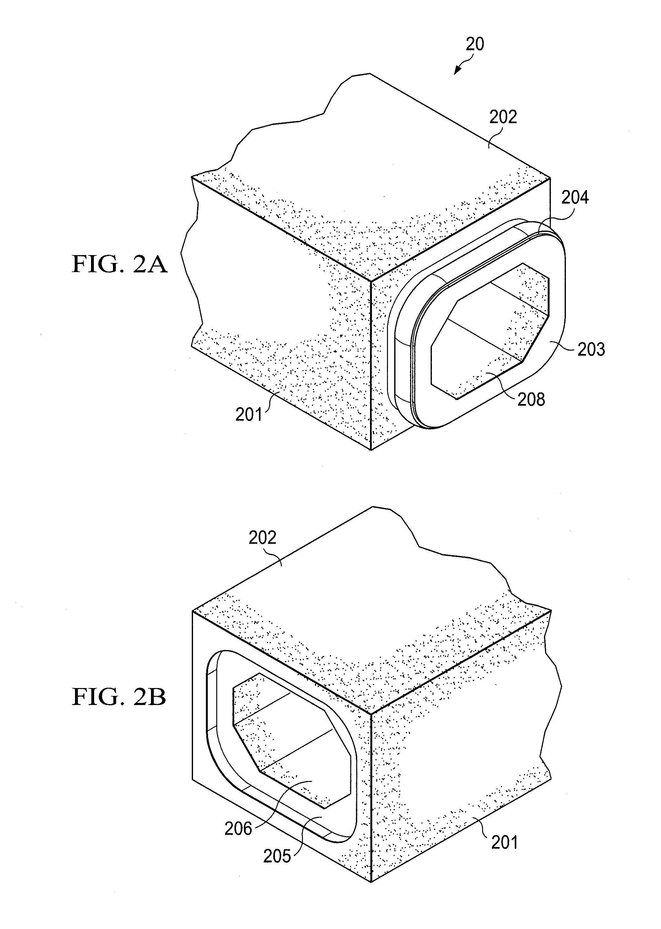
[0034]FIGS. 2A and 2B show box culvert 20. Box culvert 20 has a quadrilateral shape whereby the length of top slab 202 defines the span of box culvert 20 and the height of sidewall 201 defines the rise of box culvert 20. Specifically, the span is the horizontal inside dimension or measurement of top slab 202 and the vertical inside dimension or measurement of sidewall 201 is the rise of box culvert 20. Span normally is referred to in terms of feet and is stated before the rise dimension. For example, a 4 ft.×2 ft. box culvert has a span of 4 ft. and a rise of 2 ft. Typically, the dimensions of box culverts range from a 3 ft. span and about 2 ft. rise up to a 20 to 24 ft. span and 12 to 14 ft. rise. Box culvert 20 includes rubber gasket 204, which is used to seal the mating of male end 203 with female end 205. The mating of several box culverts 20 forms a conduit for the transportation of fluids through opening 206.

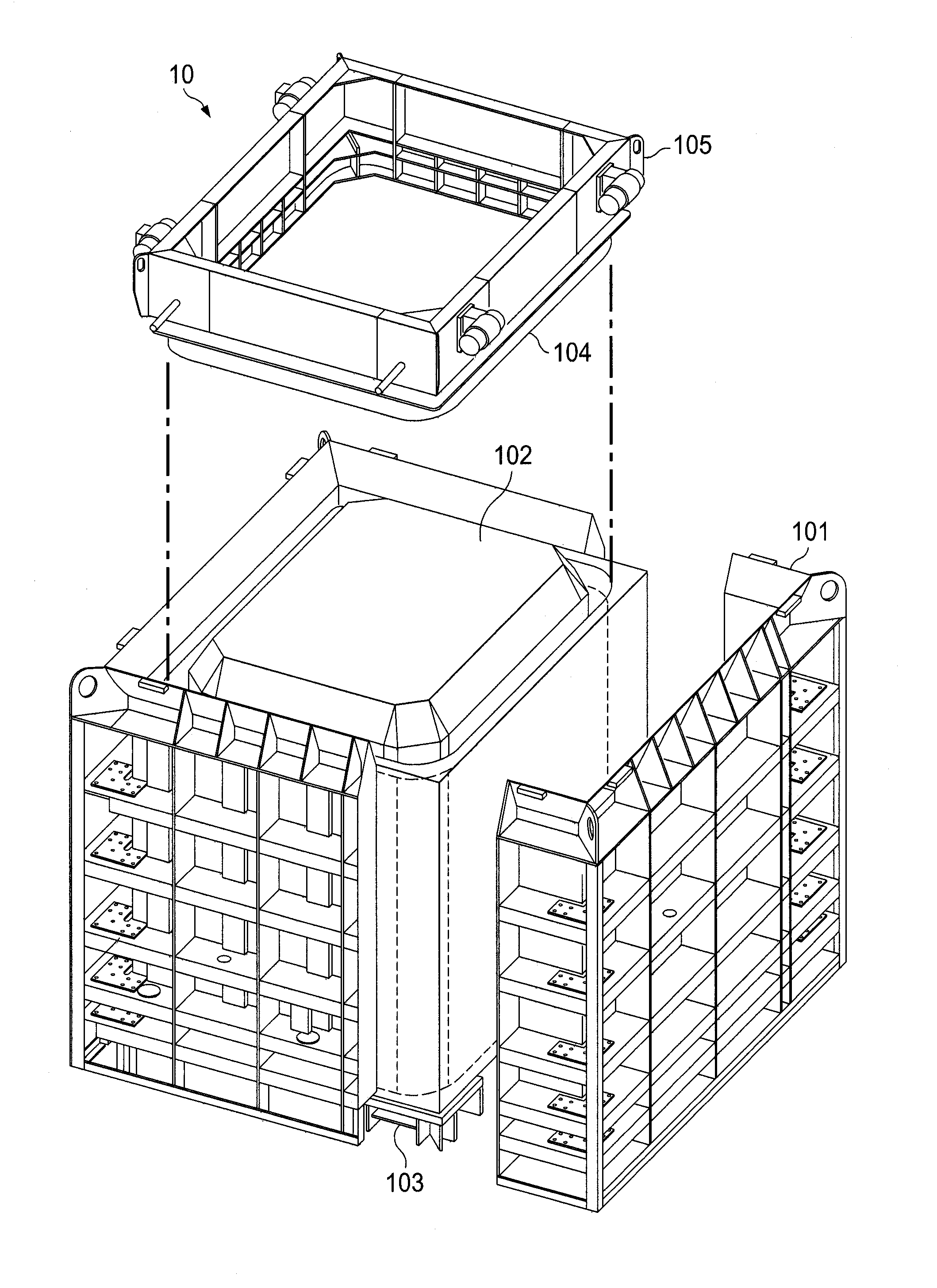
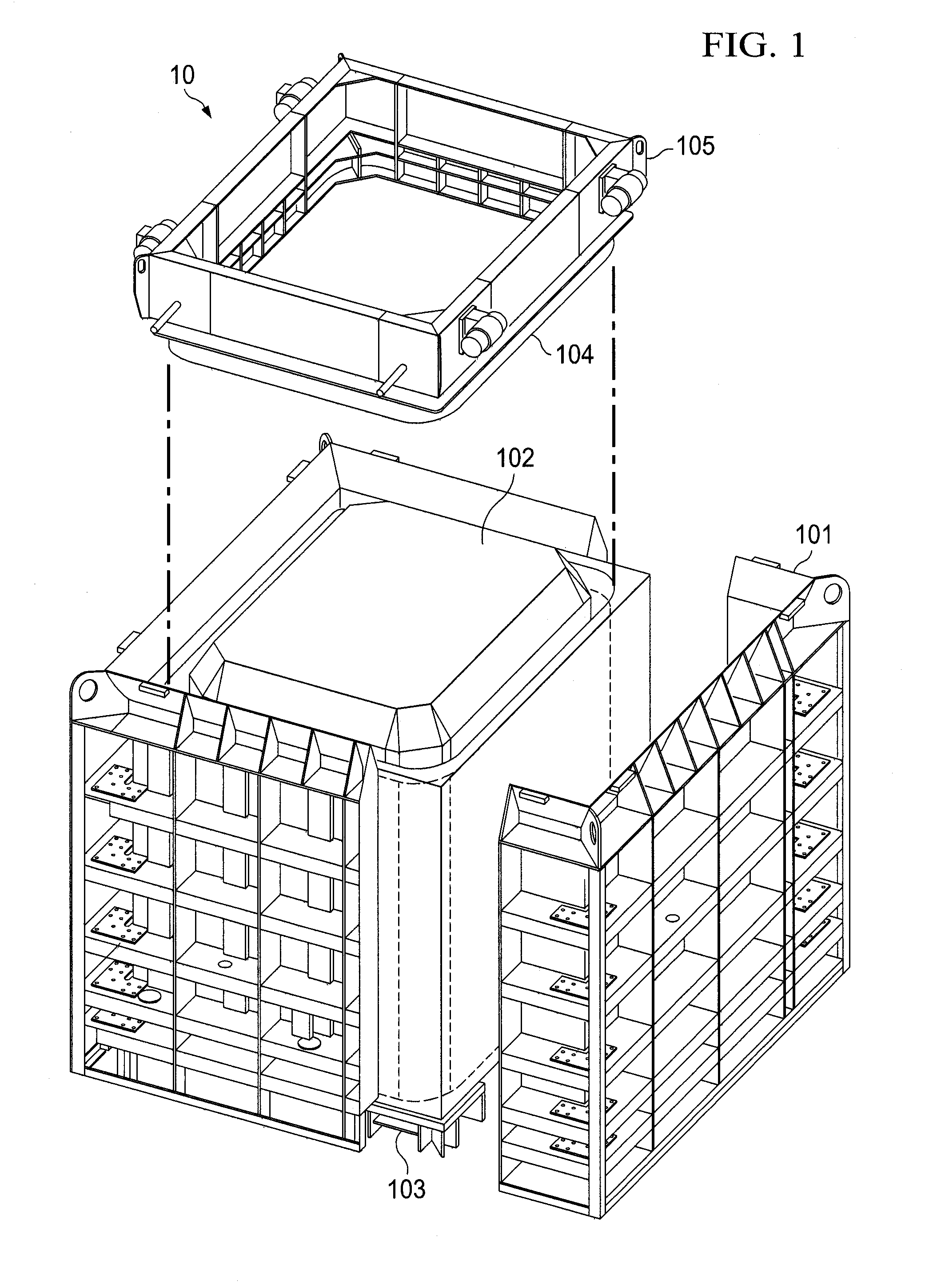
[0035]Box culvert 20 is made by pouring concrete into a mold assembly...


PUM

PropertyMeasurementUnit
lengthaaaaaaaaaa
perimeteraaaaaaaaaa
sizeaaaaaaaaaa

Abstract

Modular mold equipment for producing concrete culverts with tight tolerances. Modular mold equipment having a coupling plate is used to align and interconnect components of the mold. The components being aligned may have recesses for receiving the coupling plate. Modular mold equipment system with an extended size range to cover all standard concreted duct product sizes. Modular mold equipment having a pallet guide adjustment mechanism adapted for setting the pallet at a desired location in relation to a form. The desired location is based on a wall thickness of a concrete culvert to be produced. Modular mold equipment having a core that includes a core corner and another core component adapted to be coupled to the core corner, and locking apparatus adapted to lock the core corner to the other core component via a mechanism that extends outside the core.

Description

TECHNICAL FIELD[0001]This disclosure relates to concrete duct structures and more particularly to systems and methods for fabricating concrete duct structures using modular techniques.BACKGROUND OF THE INVENTION[0002]It is common to construct concrete duct structures that are designed to contain materials as they move from one location to another. The moving material is typically water. The ducts can be found in any environment, but usually they are placed underground to contain water movement.[0003]Concrete ducts are put together in sections, with each section having a top, bottom and sides. Each section also has a male end (tongue or spigot) and a header female end (groove or socket) which then allows sections to be put together to create an extended duct. In order to properly contain fluids from escaping out of the duct and from preventing fluids and debris from entering the duct, a gasket is fitted to the male end to serve as a seal between the male and female ends upon mating o...

Claims


Application Information

Patent Timeline
Patent Type & Authority Applications(United States)
IPC IPC(8): E02D29/063B23P17/00B23P11/00E04B1/16
CPCY10T29/4978Y10T29/49826E02D29/12B28B1/087B28B7/0014B28B7/02B28B7/18B29C33/301B29C33/306B29C45/376B29C2045/378E02D29/121E02D29/124B28B1/0873
Inventor FERGESON, L. PAUL
Owner SOUTHERN CAST PRODS
Why Eureka
Try Eureka