Projection objective lens system

Active Publication Date: 2013-09-26
SHANGHAI MICRO ELECTRONICS EQUIP (GRP) CO LTD
View PDF1 Cites 6 Cited by
  • Summary
  • Abstract
  • Description
  • Claims
  • Application Information

AI Technical Summary

Benefits of technology

The invention provides a projection objective lens system with a dual-telecentric, large-aperture structure that can handle high-quality imaging on a wafer surface. It includes a first and third flat plate to protect the lens elements and a second flat plate to compensate for any imaging quality issues. The system has a high numerical aperture, a maximum spectral width of 5 nm, and is non-sensitive to unevenness in the reticle surface. The ratio between the object and image planes and the difference between radii at the aperture stop of a marginal field beam bundle and a central field beam bundle facilitate control of distortion and even light energy distribution throughout the whole system. Its compact structure and easy assembly make it ideal for use in the ultraviolet spectral range.

Problems solved by technology

Nevertheless, a projection objective with such design has a drawback that the system has a relatively poor telecentricity, especially on an object side.
This causes the system to be extremely sensitive to the unevenness of a reticle surface, which unevenness may be generated during the fabrication of the reticle.
As a result, after it is magnified by the projection objective, even a tiny convex or concave on the reticle surface may lead to a great change in the quality and in particular the distortion of an associated image formed on a wafer surface.

Method used


Image

  • Projection objective lens system
  • Projection objective lens system
  • Projection objective lens system

Examples


Embodiment Construction

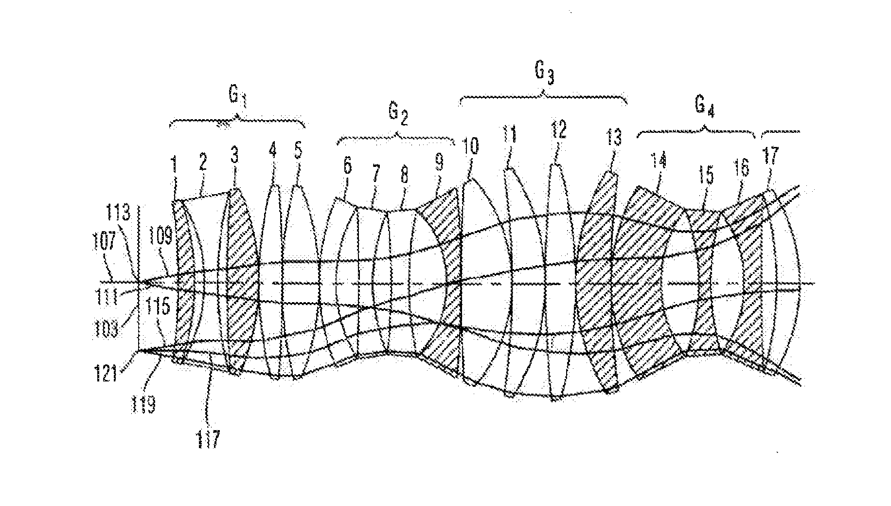
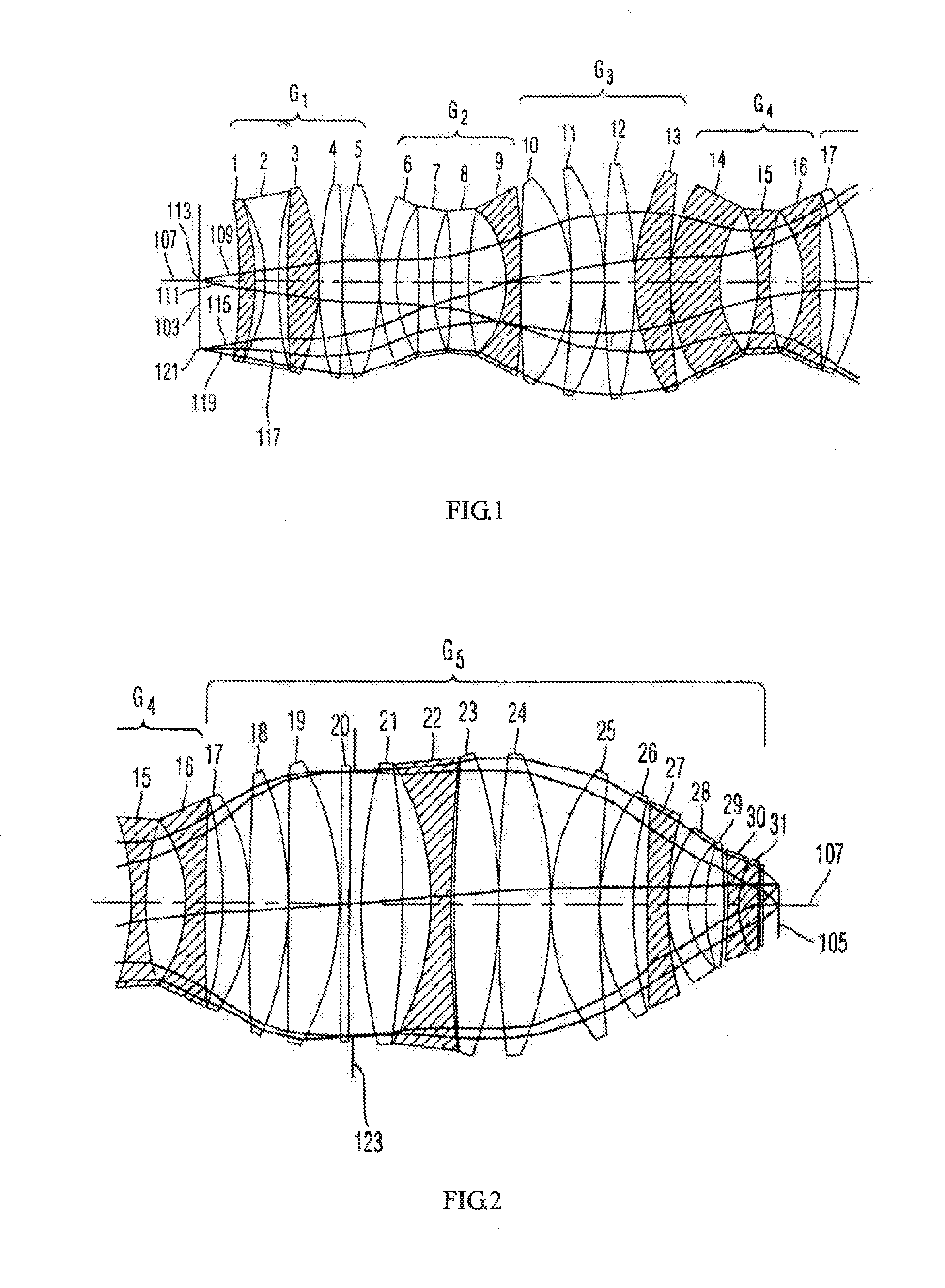
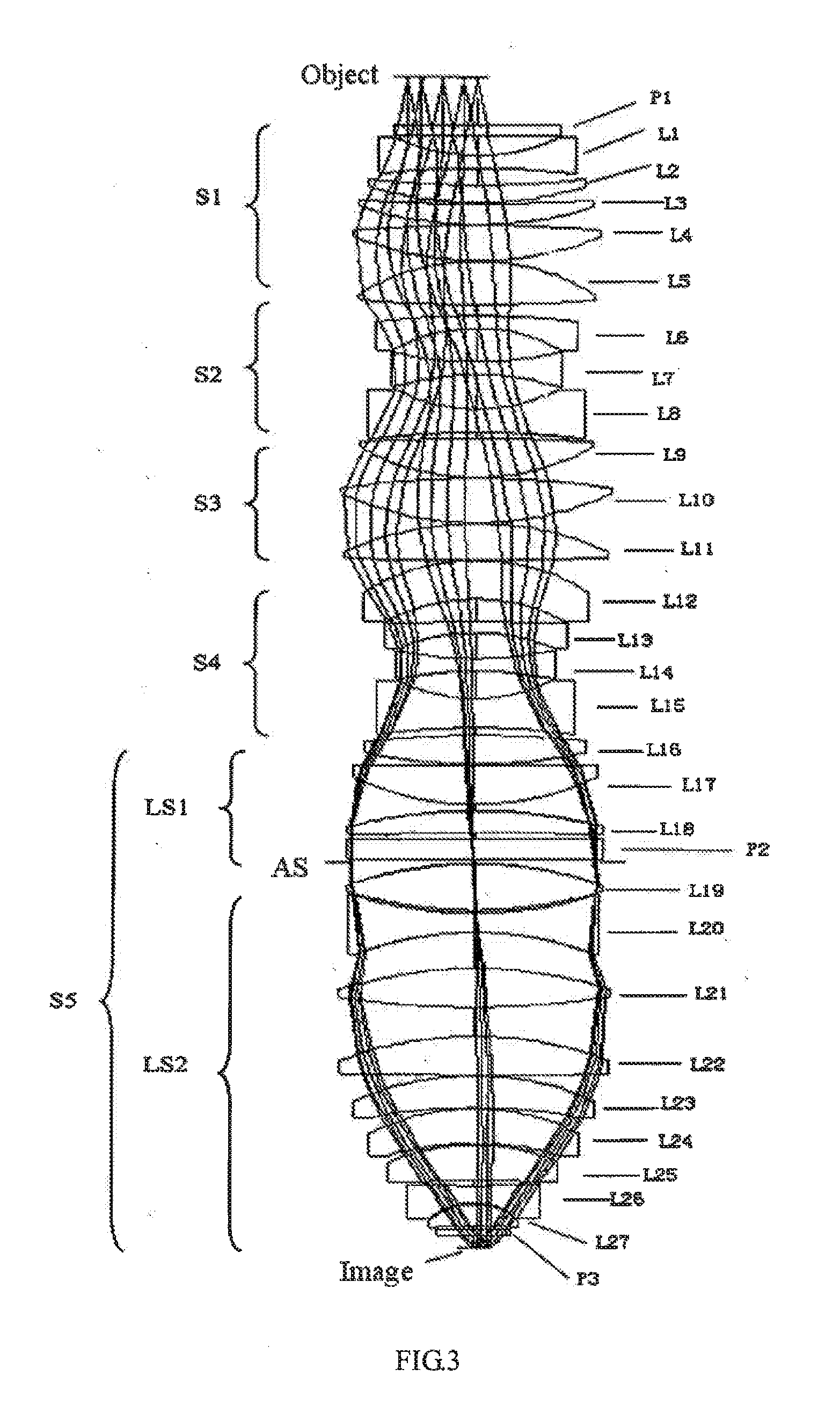
[0025]Several example embodiments of the present invention will be described below with reference to the accompanying drawings. In these figures, parts common with the conventional technologies and well known in this art are not illustrated and relevant description of them are also not given for the convenience in description and giving emphasis on describing this invention.

[0026]The projection objective according to the present invention has a total length of not greater than 1200 mm and is suited for light of the I-line with a wavelength band of 5 nm; a magnification ratio of 0.25; an image-side numerical aperture of greater than 0.5, more preferred, of greater than 0.65; an image-side diagonal field of greater than 56 mm; a ratio of a distance L between an object plane and an image plane to an effective focal length f, namely, L / f, within a range of 0.12|L / f|0.4, more preferred, within a range of 0.15|L / f|0.3. On an object side, a main beam emitted from each field point on the ob...


PUM


Abstract

A projection objective lens system includes from an object plane to an image plane: a first lens group (S1) with a positive refractive power; a second lens group (S2) with a negative refractive power; a third lens group (S3) with a positive refractive power; a fourth lens group (S4) with a negative refractive power; and a fifth lens group (S5) with a positive refractive power being divided into two sub-lens groups. An aperture stop (AS) is provided between the two sub-lens groups. The following conditions are met: 0.12<|L / f|<0.4, and ΔR / R<1%, wherein, f is an effective focal length of the system, L is a distance between the object and image planes, ΔR represents a difference between radii at the aperture stop of a marginal field beam bundle and a central field beam bundle, and R represents a radius at the aperture stop of a central field beam bundle.

Description

TECHNICAL FIELD[0001]The present invention relates in general to a projection objective lens system, and more particularly, to a projection objective lens system for use in stepper-type lithography tools for the fabrication of semiconductor chips and other miniaturized devices.BACKGROUND[0002]U.S. Pat. No. 6,806,942 proposed a so-called three-bulge two-waist projection objective system using a light source having a wavelength band with a relative width δλ / λ of larger than 0.002, or even larger than 0.005. In the system, the three bulges each have a positive refractive power and the two waists each have a negative refractive power. By selecting suitable materials, relatively high chromatic corrections are achieved, and the stability of the system is improved.[0003]FIG. 1 together with FIG. 2 shows the projection objective provided by the U.S. Pat. No. 6,806,942, which includes 31 optical elements which can be divided into 5 groups: G1, G2, G3, G4 and G5. G1-G4 are illustrated in FIG....

Claims


Application Information

Patent Timeline
IPC IPC(8): G02B13/18
CPCG02B13/24G02B13/143G02B13/18G03F7/70241G02B3/0087G02B3/04G02B27/0043G03F7/70983G02B15/145121
Inventor ZHU, LIRONG
Owner SHANGHAI MICRO ELECTRONICS EQUIP (GRP) CO LTD
Why Eureka
Try Eureka