

Flexible fiber to wafer interface
a flexible fiber and wafer technology, applied in the direction of optical elements, manufacturing tools, instruments, etc., can solve the problems of inefficiency and cost of manufacture of the previous method and device for connecting optical devices to wafer devices
- Summary
- Abstract
- Description
- Claims
- Application Information
AI Technical Summary
Benefits of technology
Problems solved by technology
Method used
Image

Examples
Embodiment Construction
[0021]Previous interfaces between optical fiber and devices arranged on wafers were costly to manufacture. The methods and devices described below offer an economic interface for connecting optical fiber to devices arranged on wafers. In this regard, a wafer may include any type of substrate having a substantially planar surface. The wafer may include any type of suitable material or combination of materials including, for example, silicon (Si), germanium (Ge), gallium (Ga), arsenic (As), indium (In), or phosphorous (P). Any type of devices or combinations of devices may be fabricated on a wafer such as, for example, optical features, optical wave guides, mechanical features, or electronic features.
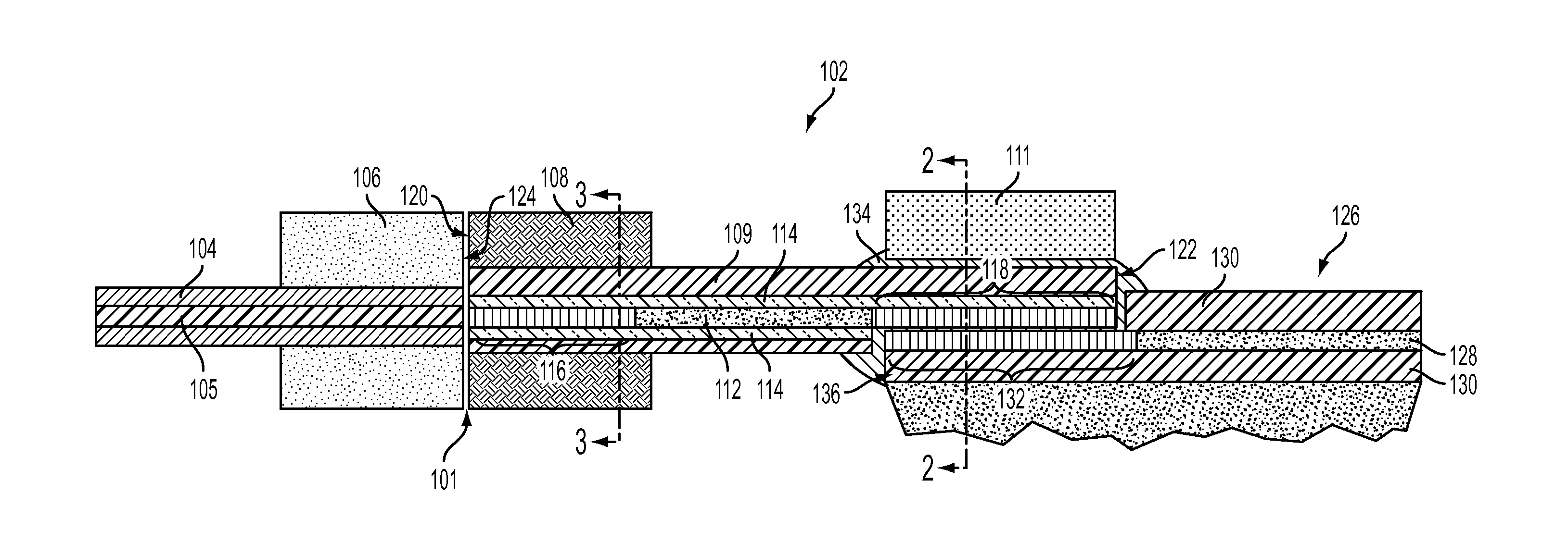
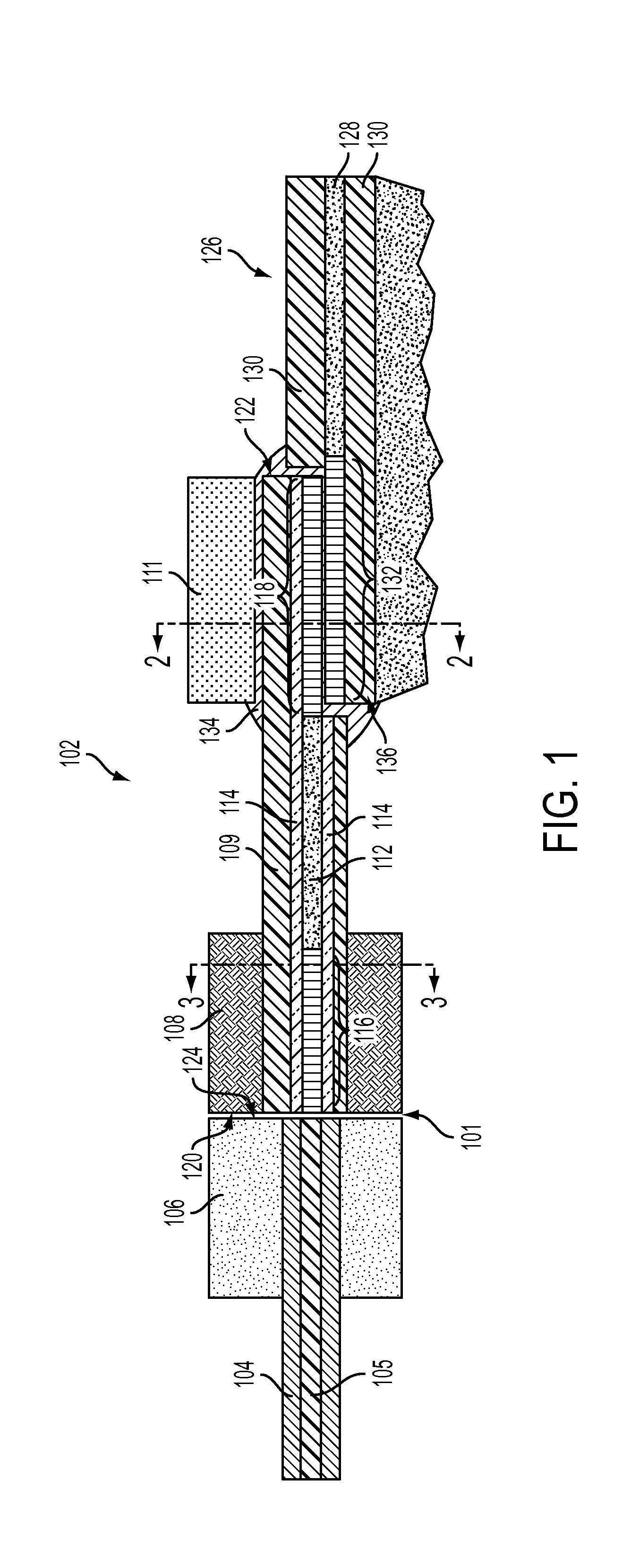
[0022]FIG. 1 illustrates a side cut-away view of an exemplary embodiment of a flexible interface device 102. The interface device 102 is secured proximate to optical fiber(s) 104 that is arranged in an optical fiber ferrule 106. The optical fiber ferrule 106 is operative to secure at leas...
PUM
| Property | Measurement | Unit |
|---|---|---|
| wavelengths | aaaaa | aaaaa |
| wavelengths | aaaaa | aaaaa |
| diameter | aaaaa | aaaaa |
Abstract
Description
Claims
Application Information