Mode beam-splitting converter based on grating-assisted coupler

A converter and coupler technology, used in light guides, optics, instruments, etc., can solve the problems of careful control and small process tolerance, and achieve the effects of convenient low-cost manufacturing, high conversion efficiency, and no beat growth.

Inactive Publication Date: 2015-09-30
LONGYAN UNIV
View PDF5 Cites 16 Cited by
  • Summary
  • Abstract
  • Description
  • Claims
  • Application Information

AI Technical Summary

Problems solved by technology

The mode converters currently proposed are mainly based on two structures: the first is the directional coupler structure, which can realize the separation and conversion of the two modes through the effective refractive index matching method, but its disadvantage is that there is a strict beat The length of the device needs to be carefully controlled; the second is based on the combin

Method used


Image

  • Mode beam-splitting converter based on grating-assisted coupler
  • Mode beam-splitting converter based on grating-assisted coupler
  • Mode beam-splitting converter based on grating-assisted coupler

Examples


Embodiment

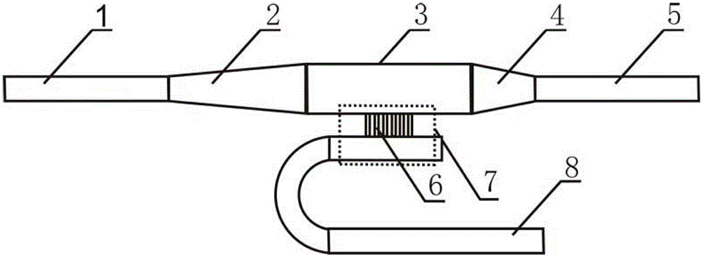
[0032] Such as figure 1 with Figure 4 As shown, the silicon-on-insulator (SOI) material with a thickness of 220nm on the top layer of silicon and a buried silicon dioxide layer of 2μm is used. After cleaning the wafer surface, perform deep ultraviolet lithography or electron beam direct writing lithography to obtain silicon etching. Mask, through silicon dry etching twice, a single-mode silicon ridge waveguide with a width of 450nm, a multi-mode ridge waveguide with a width of 850nm, a gradient ridge waveguide with a width of 450nm to 850nm, a length of 100um and a width of 850nm are produced. It is a graded ridge waveguide with a length of 450nm and a length of 50um, and the outer ridge height of the ridge waveguide is 60nm. Bragg waveguide gratings 6 are etched on one side of the bus multimode waveguide 3 and the drop single-mode waveguide 8 , the rectangular grating teeth are 100nm and 50nm respectively, and the period of the grating is 344nm.

[0033] The grating period...


PUM


Abstract

The invention discloses a mode beam-splitting converter based on a grating-assisted coupler. The converter comprises a single-mode input waveguide, an input mode converter, a bus multi-mode waveguide, a downlink Bragg waveguide grating, an output mode converter, a single-mode output waveguide, a downlink single-mode waveguide and a downlink coupling zone, wherein the input mode converter converts a TM (transverse magnetic) mode in the single-mode input waveguide into a TE (transverse electric) first-order mode in the bus multi-mode waveguide, and by the aid of the Bragg waveguide grating assisted coupler, the TE first-order mode of the multi-mode waveguide and the TE mode of the single-mode waveguide exchange energy. The converter realizes separation of the TE mode and the TM mode which are transmitted in the waveguide, converts the TM mode into the TE mode and has the advantages of simple structure, compactness, large work bandwidth, low crosstalk and the like, the production technology has CMOS (complementary metal-oxide-semiconductor) technology compatibility, the device is easy to integrate and extend, low-cost production is facilitated, and the device can be widely applied to on-chip high-density-integrated optical interconnection systems.

Description

technical field [0001] The invention relates to an integrated optical mode beam splitting conversion device, in particular to a mode beam splitting converter based on a grating-assisted coupler. Background technique [0002] With the rapid development of today's society, people's demand for network data volume continues to increase, so the requirement to increase the speed of communication networks has become an urgent problem to be solved. Optical communication networks have achieved great success and are currently moving towards the goal of low cost, large capacity and high speed. Now the optical transport network of 40Gb / s has been widely used, and the optical network of 100Gb / s is in the vigorous development stage. A consensus has been reached on the adoption of a standardized codec method in an optical network with a speed exceeding 100Gb / s. This codec method is based on the coherent reception dual-polarization quadrature phase-shift keying modulation technique (PM-QPS...

Claims


Application Information

Patent Timeline
IPC IPC(8): G02B6/126G02B6/14
CPCG02B6/126G02B6/14
Inventor 邱晖晔赖国忠苏玉霞
Owner LONGYAN UNIV
Why Eureka
Try Eureka