Eureka AIR delivers breakthrough ideas for toughest innovation challenges, trusted by R&D personnel around the world.

Method and control unit for metering fuel into an exhaust gas duct

Active Publication Date: 2013-09-26
ROBERT BOSCH GMBH
View PDF6 Cites 9 Cited by
  • Summary
  • Abstract
  • Description
  • Claims
  • Application Information

AI Technical Summary

Benefits of technology

The invention relates to a method for reducing tolerances in fuel injection. This is achieved by controlling the fuel pressure during injection so that it remains constant within a certain range. By not actuating the high pressure pump when the fuel pressure is too high, the amount of fuel injected is reduced, and by actuating the pump when the fuel pressure is too low, the amount of fuel injected is increased, resulting in a more accurate injection of fuel. This method prevents oscillations in the control loop and ultimately reduces tolerances in the actual fuel injected.

Problems solved by technology

As a result of the soot masses embedded in the filter substrate, the particle filter becomes clogged with time.

Method used


Image

  • Method and control unit for metering fuel into an exhaust gas duct
  • Method and control unit for metering fuel into an exhaust gas duct
  • Method and control unit for metering fuel into an exhaust gas duct

Examples


Embodiment Construction

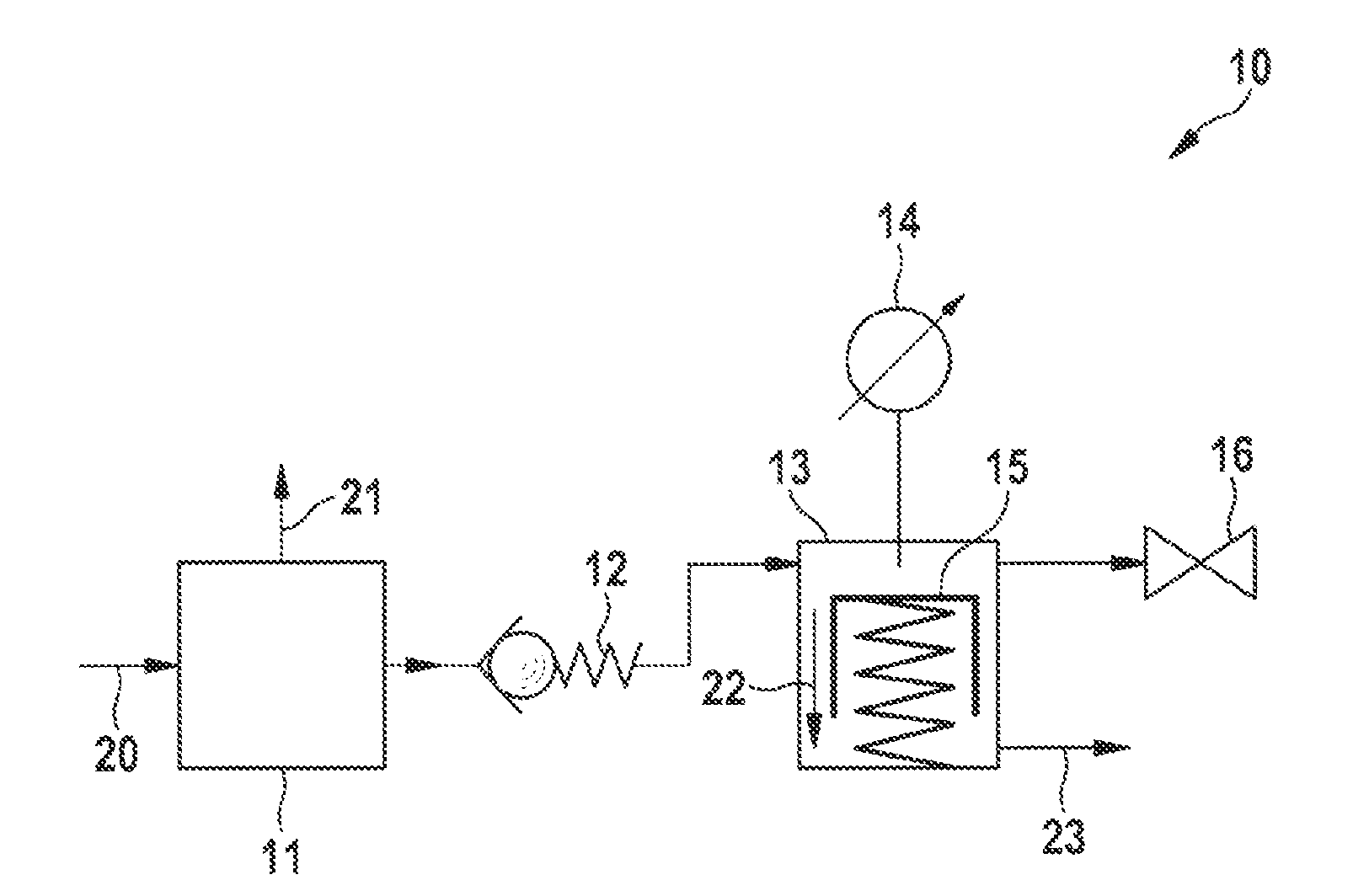
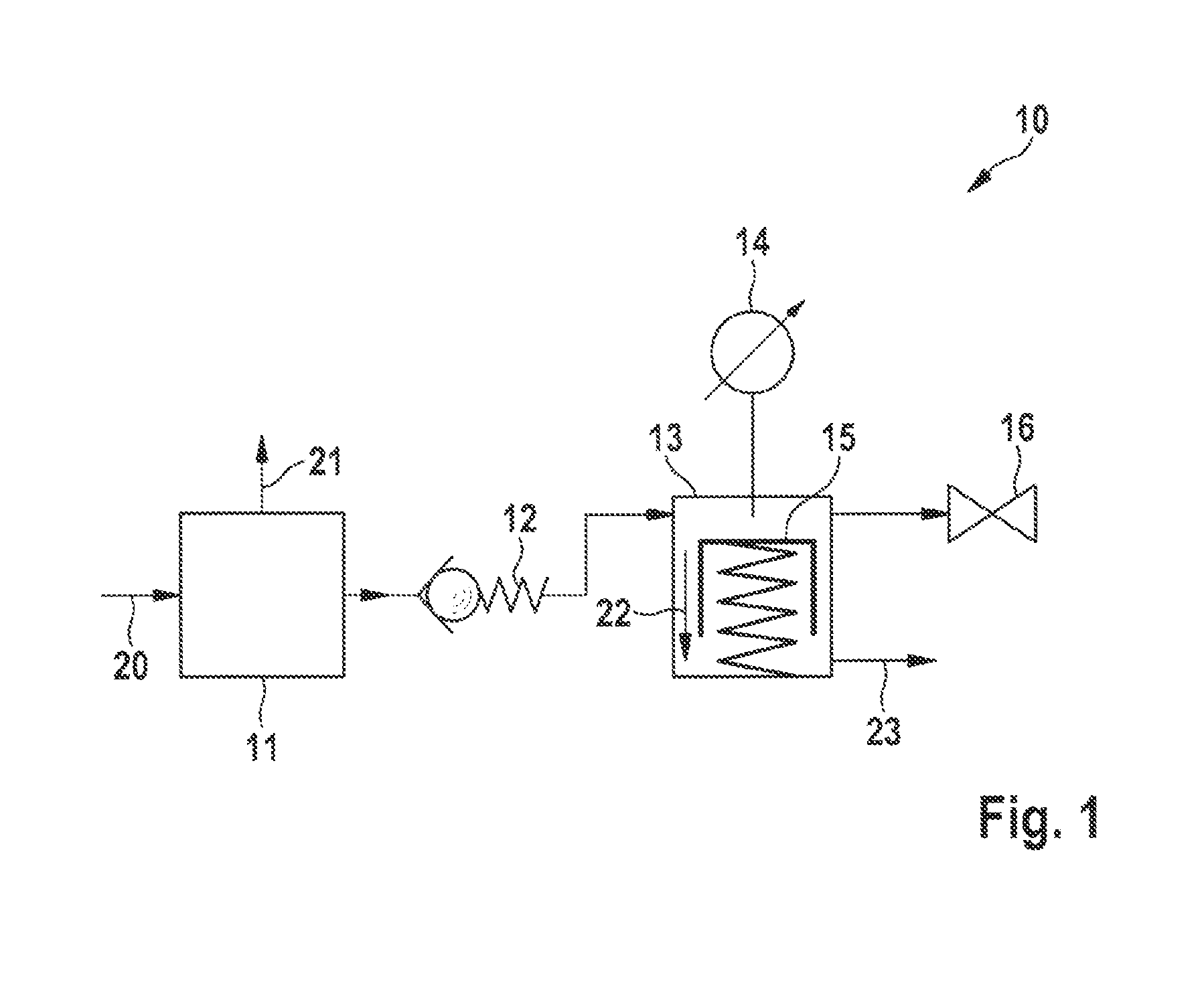
[0031]FIG. 1 shows a high pressure system 10 for introducing fuel into a non-depicted exhaust gas duct of a diesel engine in schematic depiction. Fuel, which is compressed to a pressure of 30 bar via a high pressure pump 11, is supplied to the high pressure system 10 via a low pressure fuel supply 20. The high pressure pump 11 is embodied as a magnetically operated HCI pump, which discretely delivers fuel and has a constant stroke volume. The compressed fuel arrives at a pressure accumulator 13 in the form of a piston accumulator via a pressure valve 12, the pressure of the fuel that has built up being maintained by a piston in said piston accumulator. The fuel pressure is determined using a pressure measuring device 14. The fuel is metered into the exhaust gas duct with a high pressure injection valve 16.

[0032]Disturbance variables are leaks in the high pressure system 10. Thus, a first fuel leak 21 at the high pressure pump 11 and a second fuel leak 22 at the pressure accumulator ...


PUM


Abstract

A method for metering fuel from a high pressure system, comprising at least one high pressure pump, one pressure accumulator and one high pressure injection valve, into an exhaust gas duct of an internal combustion engine in order to regenerate a nitrogen oxide storage catalyst (NSC) disposed in the exhaust gas duct, wherein a higher pressure of the fuel is generated by the electrically actuated high pressure pump, which discretely delivers fuel and has a constant stroke volume, wherein the fuel is supplied to the pressure accumulator comprising a pressure measuring device for determining the fuel pressure and wherein the fuel is injected into the exhaust gas duct via the downstream, electrically actuated high pressure injection valve.

Description

BACKGROUND OF THE INVENTION[0001]The invention relates to a method for metering fuel from a high pressure system, comprising at least one high pressure pump, one pressure accumulator and one high pressure injection valve, into an exhaust gas duct of an internal combustion engine in order to regenerate a nitrogen oxide storage catalytic converter disposed in the exhaust gas duct, wherein a high pressure of the fuel is generated by the electrically actuated high pressure pump, which discretely delivers the fuel and has a constant stroke volume, wherein the fuel is supplied to the pressure accumulator comprising a pressure measuring device for determining the fuel pressure and wherein the fuel is injected into the exhaust gas duct via the downstream, electrically actuated high pressure injection valve.[0002]The invention relates further to a method for metering fuel from a high pressure system, comprising at least one high pressure pump, one pressure accumulator and one high pressure i...

Claims


Application Information

Patent Timeline
IPC IPC(8): F04B23/04
CPCF04B13/00F04B23/04F01N3/0814F01N3/0842F01N3/0871F01N3/36F01N2900/1808F01N2610/144Y02T10/47F01N9/002F01N11/00F01N2550/05F01N2610/03Y02T10/40
Inventor KELLNER, ANDREAS
Owner ROBERT BOSCH GMBH
Why Eureka
Eureka Blog
Learn More