Model Based Approach For In-Situ WVTD Degradation Detection In Fuel Cell Vehicles

a fuel cell and degradation detection technology, applied in the field of model based approach for in-situ wvtd degradation detection in fuel cell vehicles, can solve the problems of insufficient identification of issues related to wvt unit degradation or wear, poor electrical performance, premature cell failure, etc., and achieve the effect of accurate way to estimate and control relative humidity and loss of wvt unit effectiveness

Inactive Publication Date: 2013-09-26
GM GLOBAL TECH OPERATIONS LLC
View PDF4 Cites 7 Cited by
  • Summary
  • Abstract
  • Description
  • Claims
  • Application Information

AI Technical Summary

Benefits of technology

[0006]According to one aspect of the invention, a method of in-situ WVT unit degradation detection or estimation includes using a combination of a backward-looking (i.e., reverse) model and a forward-looking model. In the present context, in-situ activities are those that are conducted without requiring the WVT unit to be removed from the fuel cell stack or system with which it is operative; as such, measurements and related determinations or predictions may be made while the fuel cell stack or system is operative, or at least without having to remove or otherwise decouple the WVT unit from the remainder of the fuel cell system. Using such models (the first for the unit itself and the second for stack HFR and hydration) as a basis for stack water management is a more accurate way to estimate and control relative humidity for both stack inlet and outlet conditions than through a mere averaging technique. For example, a

Problems solved by technology

On the other hand, too little hydration limits the conductivity of the ion-transmissive membrane that is disposed between catalyzed electrodes; this high ionic resistance can lead to poor electrical performance, as well as premature cell failure.
While determining an HFR between stack terminals may provide a good measure of average stack membrane relative humidity for helping to meet stack efficiency targets, it is not sufficient for identifying issues

Method used


Image

  • Model Based Approach For In-Situ WVTD Degradation Detection In Fuel Cell Vehicles
  • Model Based Approach For In-Situ WVTD Degradation Detection In Fuel Cell Vehicles
  • Model Based Approach For In-Situ WVTD Degradation Detection In Fuel Cell Vehicles

Examples


Embodiment Construction

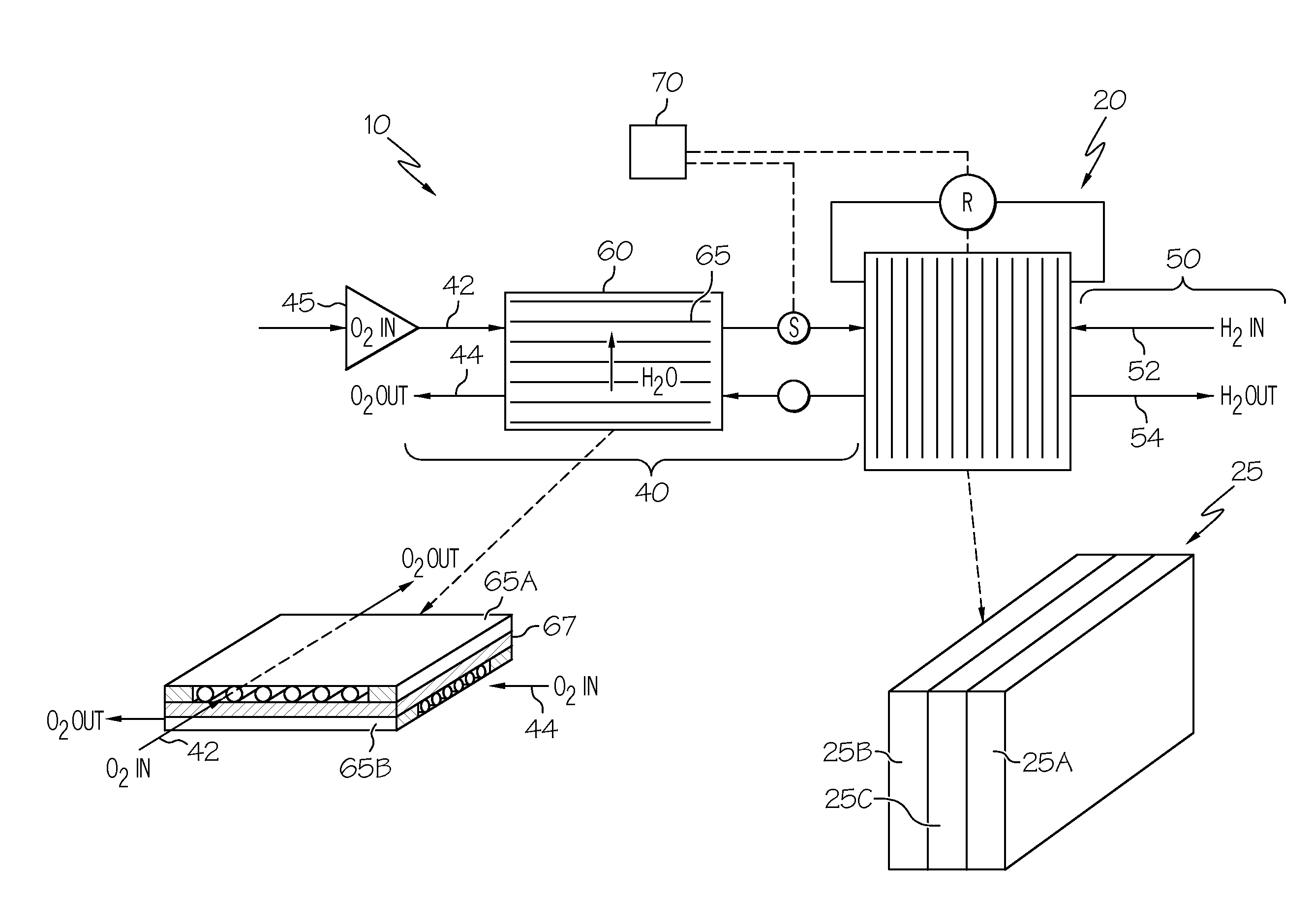
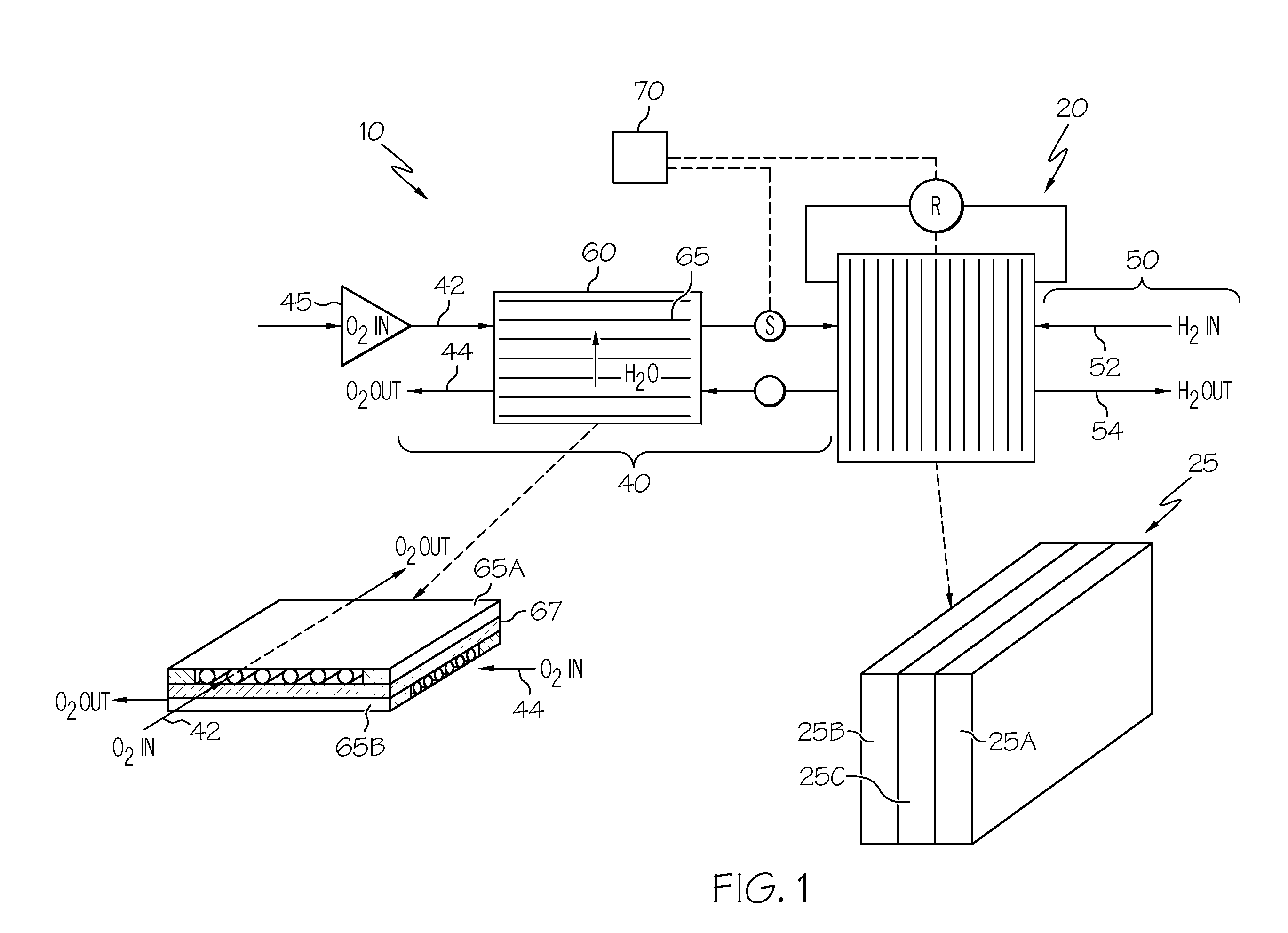
[0016]Referring first to FIGS. 1 and 5, a fuel cell system 10 includes a fuel cell stack 20 made up of numerous individual fuel cells 25, each of which has an anode 25A and cathode 25B separated by an ion-transmissive membrane 25C, as well as an automobile 1 being powered by fuel cell stack 20 is shown. As will be understood by those skilled in the art, numerous such cells 25 are combined to form the stack 20 such that the power generation is increased. Likewise, numerous such stacks 20 may be used. Referring with particularity to FIG. 1, various flowpaths 40, 50 are used to convey reactants and their byproducts to and from the stack 20. A WVT unit 60 is fluidly coupled to either or each of the respective flowpaths 40, 50 to promote the balanced humidity levels within one or both of them. As shown with particularity for the cathode-side reactant (i.e., an oxygen-bearing fluid), dry air from a compressor 45 is fed through an inlet flowpath 42 into the WVT unit 60 Likewise, stack cath...


PUM


Abstract

A method of estimating water vapor transfer unit degradation without having to remove the unit from a fuel cell system to which it cooperates, and a device performing the same. The method includes using a combination of a backward-looking model and a forward-looking model. The first of these models is used to evaluate changes in water vapor transfer effectiveness in the unit, while the second is for determining the water transfer rate of the unit. Together, the models provide a more accurate way to estimate and control relative humidity for both stack inlet and outlet flowpaths, as well as provide an indication of when service or replacement of the water vapor transfer unit may be warranted.

Description

BACKGROUND OF THE INVENTION[0001]The present invention relates generally to monitoring a water vapor transfer (WVT) device used in a fuel cell system, and more particularly to using one or more hydration models to permit in-situ monitoring and evaluation of performance characteristics of the WVT device.[0002]Fuel cells, particularly proton exchange membrane or polymer electrolyte membrane (in either event, PEM) fuel cells, require balanced water levels to ensure proper operation. For example, it is important to avoid having too much water in the fuel cell, which can result in the flooding or related blockage of the reactant flowfield channels. On the other hand, too little hydration limits the conductivity of the ion-transmissive membrane that is disposed between catalyzed electrodes; this high ionic resistance can lead to poor electrical performance, as well as premature cell failure. One popular way to promote proper levels of humidification or related water balance within the fue...

Claims


Application Information

Patent Timeline
IPC IPC(8): H01M8/04G06F19/00G01N19/10
CPCH01M8/04828H01M8/04992H01M8/04141Y02E60/50H01M8/04492H01M8/04686H01M8/04149
Inventor ZHANG, YANSINHA, MANISHDEVRIES, LOREN
Owner GM GLOBAL TECH OPERATIONS LLC
Why Eureka
Try Eureka