Vehicle steering control apparatus

a technology for steering control and vehicles, applied in the direction of steering initiation, instruments, vessel construction, etc., can solve the problems of failure of one electronic control unit and the apparatus disclosed in the patent document 1 that does not provide any solutions, and achieve the effect of increasing driving force, promoting the change of slip angle, and large braking for

Active Publication Date: 2013-09-26
TOYOTA JIDOSHA KK
View PDF1 Cites 46 Cited by
  • Summary
  • Abstract
  • Description
  • Claims
  • Application Information

AI Technical Summary

Benefits of technology

[0051]Moreover, if the braking / driving force varying apparatus is a braking force varying apparatus, braking forces, preferably as friction braking forces applied to the left and right wheels, are varied. This can provide the same effect as relatively increasing the driving force, for the wheel on the side where a smaller braking force is applied. In other words, the braking force is a so-called negative driving force.
[0052]In any case, if there is the braking / driving force difference between the left and right wheels, the vehicle turns to the side of the wheel having a relatively small driving force (i.e. the wheel having a relatively large braking force) (i.e. to the right side if the driving force (or braking force) on the right wheel side is small (or large)). Therefore, according to the braking / driving force varying apparatus, theoretically, the direction of travel of the vehicle can be changed independently of the driver's steering input. In other words, the braking / driving force varying apparatus is also preferable as the apparatus which promotes the change in the slip angle and the yaw rate.

Problems solved by technology

However, a failure of the one apparatus, as described in paragraph, means a failure of one electronic control unit (ECU), and does not mean a failure of a mechanism which changes the state controlled variable (e.g. a steering angle) which promotes a change in the vehicle state quantities including the slip angle and the yaw moment.
In other words, the apparatus disclosed in the Patent document 1 does not provide any solutions if the number of the independently controllable state controlled variables is reduced, for example, due to temporal or permanent malfunction of the apparatus or the like, or due to the other circumstances.

Method used


Image

  • Vehicle steering control apparatus
  • Vehicle steering control apparatus
  • Vehicle steering control apparatus

Examples


first embodiment

1: First Embodiment

1-1: Configuration of Embodiment

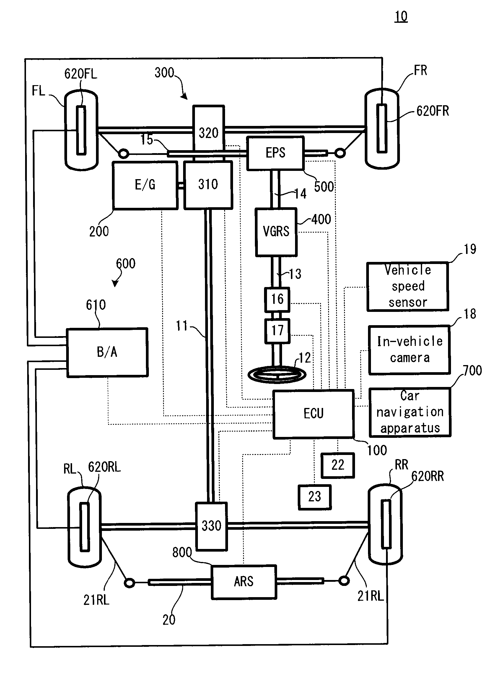
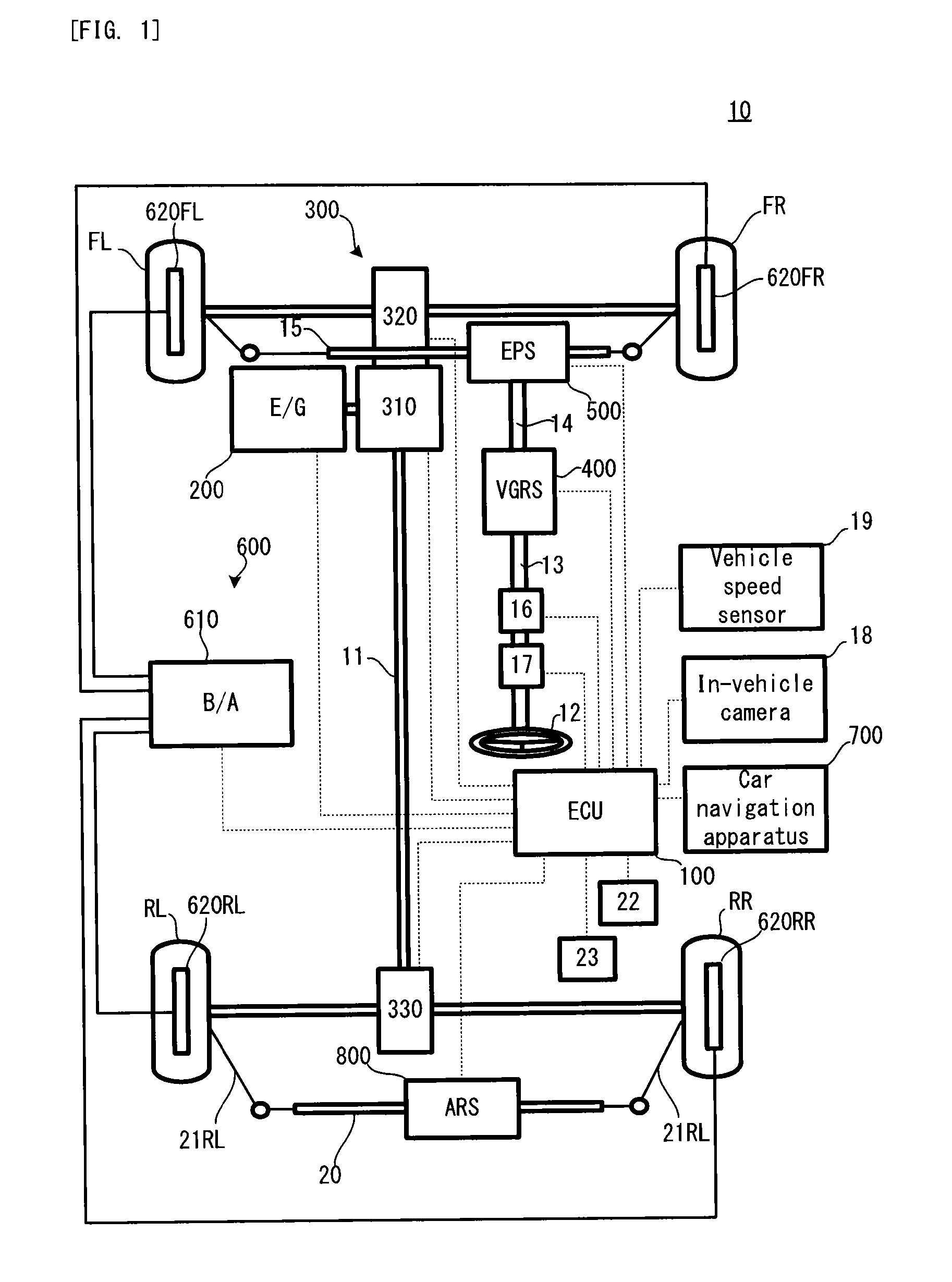
[0100]Firstly, with reference to FIG. 1, a configuration of a vehicle 10 in a first embodiment of the present invention will be explained. FIG. 1 is a schematic configuration diagram conceptually illustrating a basic configuration of the vehicle 10.

[0101]In FIG. 1, the vehicle 10 is provided with a left front wheel FL, a right front wheel FR, a left rear wheel RL and a right rear wheel RR. The vehicle 10 is configured to move in a desired direction by a steering angle change of the left front wheel FL and the right front wheel FR, which are steered wheels, and a steering angle change of the left rear wheel RL and the right rear wheel RR.

[0102]The vehicle 10 is provided with an ECU 100, an engine 200, a driving force distributing apparatus 300, a VGRS actuator 400, and EPS actuator 500, an electronic controlled braking system (ECB) 600, a car navigation apparatus 700, and an ARS actuator 800.

[0103]The ECU 100 is provided with a centr...

second embodiment

2: Second Embodiment

[0223]Next, with reference to FIG. 5, fail-safe control in a second embodiment of the present invention will be explained. FIG. 5 is a flowchart illustrating the fail-safe control in the second embodiment. Incidentally, in FIG. 3, portions overlapping those of FIG. 4 will carry the same reference numerals, and the explanation thereof will be omitted as occasion demands.

[0224]In FIG. 5, if the vehicle behavior is stable and if the vehicle 10 is not turning (the step S204: NO), the ECU 100 further determines whether or not a turning degree change rate is large (step S301). More specifically, the ECU 100 determines whether or not a change rate Δγ of the yaw rate γ is greater than or equal to a reference value Δγth. If the turning degree change rate is small (the step S301: NO), the ECU 100 moves the processing to the step S206 and selects the slip angle 13 as the vehicle state quantity. If the turning degree change rate is large (the step S301: YES), the ECU 100 mov...

third embodiment

3: Third Embodiment

[0226]Next, with reference to FIG. 6, fail-safe control in a third embodiment of the present invention will be explained. FIG. 6 is a flowchart illustrating the fail-safe control in the third embodiment. Incidentally, in FIG. 6, portions overlapping those of FIG. 4 will carry the same reference numerals, and the explanation thereof will be omitted as occasion demands.

[0227]In FIG. 6, if the vehicle behavior is stable and if the vehicle 10 is not turning (the step S204: NO), the ECU 100 further determines whether or not a steering state of the vehicle 10 is strong under-steering (step S401). More specifically, the ECU 100 determines whether or not the degree of an outward deviation in the turning of the vehicle 10 with respect to the target driving route in the trajectory following control is greater than or equal to a reference value. The determination as described above can be performed on the basis of the yaw angle deviation φ and the driving route radius R or t...


PUM


Abstract

A vehicle motion control apparatus which is configured to control a motion of a vehicle comprising a plurality of apparatuses, each of which is configured to selectively control a slip angle or a yaw rate, is provided with: a behavior controlling device which is configured to perform behavior control in which a plurality of apparatuses are controlled such that a slip angle and a yaw rate are a set target slip angle and a target yaw rate, respectively; a turning state quantity specifying device which is configured to specify a turning state quantity of the vehicle; and a selecting device which is configured to select at least one of the slip angle and the yaw rate to be prioritized, on the basis of the specified turning state quantity in a case where the behavior control needs to be performed by one of the plurality of apparatuses. The behavior controlling device controls the one apparatus such that the selected one has the target value corresponding to the selected one, in the case where the behavior control needs to be performed by the one apparatus.

Description

TECHNICAL FIELD[0001]The present invention relates to a vehicle motion control apparatus which can be applied to a vehicle provided with various automatic driving functions such as, for example, lane keeping assist (LKA).BACKGROUND ART[0002]As this type of apparatus, there is a vehicle motion control apparatus disclosed in Patent document 1. According to this apparatus, in a case where slip angle control and yaw moment control are performed by different apparatuses, if one of the apparatuses has broken down, the other apparatus performs control for compensating the broken-side control.[0003]Incidentally, it is also proposed that in control for coordinating a vehicle behavior stabilization control device (VSA) and a rear-wheel tow angle control device (RTC), each of the VSA and the RTC performs the control on the basis of a yaw rate obtained from a coordinated control unit in the normal case of the coordinated control unit, and each of the VSA and the RTC performs the control on the ...

Claims


Application Information

Patent Timeline
Patent Type & Authority Applications(United States)
IPC IPC(8): B60W30/02B60W10/20B60W10/18
CPCB62D6/003B60W50/035B60W10/20B60W30/045B60W2050/009B60W2720/14B60W2720/20B60W30/02B60W30/12B62D7/159B62D15/025B60W50/023B60W10/188B60W2720/406B60W50/02B60W10/18
Inventor NISHIKAWA, NORIHISATANIMOTO, MITSUTAKAFUJITA, YOSHITAKATAKASHIMA, TORUNARITA, TETSUHIROINOUE, GOKOJO, TAKAHIRO
Owner TOYOTA JIDOSHA KK
Why Eureka
Try Eureka