Microfluidic system

Inactive Publication Date: 2013-10-03
OCTROLIX
View PDF1 Cites 3 Cited by
  • Summary
  • Abstract
  • Description
  • Claims
  • Application Information

AI Technical Summary

Benefits of technology

[0006]The present invention provides a microfluidic channel that avoids some of the costs and disadvantages of the prior art. In particular, the present invention provides a microfluidic channel that exhibits analyte flow charact

Problems solved by technology

Unfortunately, for many analytes, fused silica exhibits poor flow characteristics.
In particular, fused silica can induce a large degree of flow velocity variation within an analyte plug, which can cause the analyte plug to “smear out

Method used


Image

  • Microfluidic system
  • Microfluidic system
  • Microfluidic system

Examples


Embodiment Construction

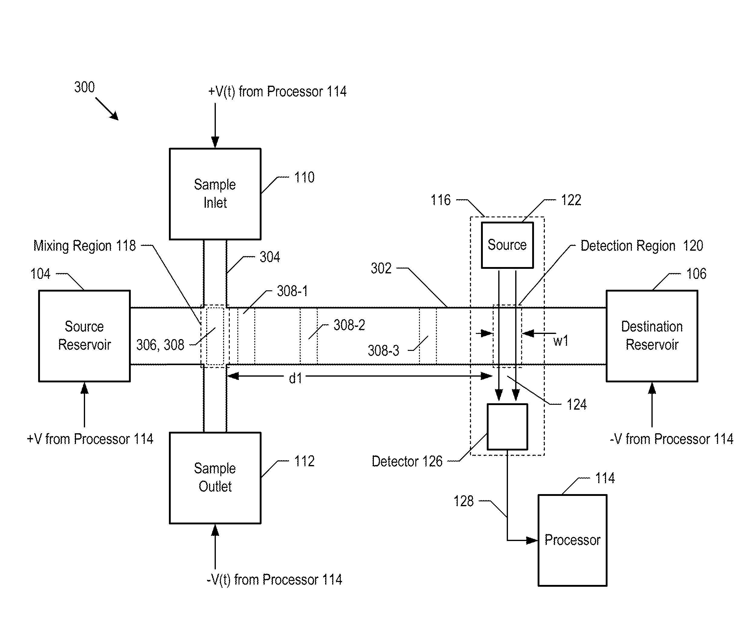
[0019]In the illustrative embodiment of the present invention, a capillary electrophoresis (CE) system based on surface-modified microfluidic channels is used to detect the presence of an analyte in a solution. A CE system is one example of a microfluidic system for which the present invention is suitable. Precise detection of the presence and / or concentration of an analyte at a location in a microfluidics system is important in many microfluidic applications, such as lab-on-a-chip, microreactors, analytic systems, capillary electrophoresis, and the like.

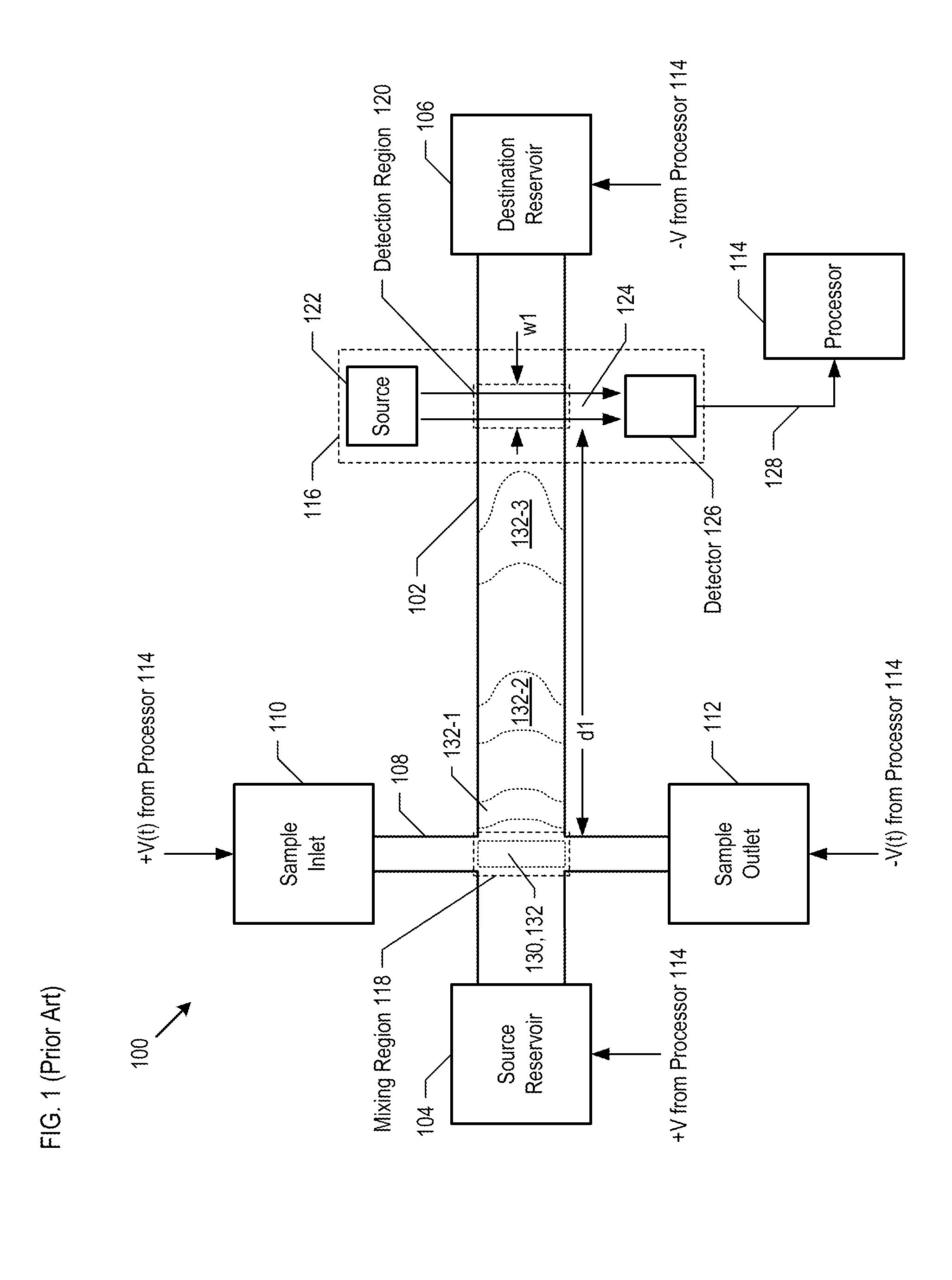
[0020]FIG. 1 depicts a schematic diagram of details of a capillary electrophoresis system (hereinafter, CE system) in accordance with the prior art. CE system 100 comprises flow channel 102, source reservoir 104, destination reservoir 106, sample channel 108, sample inlet 110, sample outlet 112, processor 114, and sensor 116.

[0021]Capillary electrophoresis is a well-known technique for analyzing samples of chemicals, cells, and biol...


PUM

PropertyMeasurementUnit
Shapeaaaaaaaaaa

Abstract

A method for forming a microfluidic channel with improved flow characteristics for one or more analytes is disclosed. A microfluidic channel having modified surfaces is formed in a glass layer or glass substrate. The glass surfaces of the microfluidic channel are modified by the addition of a layer of borophosphosilicate glass. The addition of the borophosphosilicate glass results in an improved flow velocity profile of the analyte. As a result, control over the position and movement of analytes within the solution is improved.

Description

CROSS REFERENCE TO RELATED APPLICATIONS[0001]This case is a continuation-in-part of co-pending U.S. patent application Ser. No. 12 / 172,740, filed Jul. 14, 2008 (Attorney Docket: 145-010US), which is incorporated by reference herein.FIELD OF THE INVENTION[0002]The present invention relates to microfluidics in general, and, more particularly, to the formation of microfluidic channels.BACKGROUND OF THE INVENTION[0003]Microfluidic systems offer potential advantage in applications such as chemical synthesis, distillation, and analysis. Such systems typically include one or more flow channels interconnected to chambers where minute volumes of fluids are introduced, extracted, separated, reacted, or dissociated into constituent components. In order for a microfluidic system to operate properly, the flow of analytes contained in the solutions that flow through the flow channels must be carefully controlled.[0004]Often, a microfluidic system distributes buffered electrolyte containing one or...

Claims


Application Information

Patent Timeline
IPC IPC(8): B01L3/00B81B1/00G01N27/447
CPCB01L3/502707G01N27/44791B81B1/00B01L3/5027Y10T156/10C03C17/02B01L2300/12B01L2400/0415G01N27/44743B01L3/569
Inventor HEIDEMAN, RENE GERRIT
Owner OCTROLIX
Why Eureka
Try Eureka