Apparatus and method for forming electrical solder connections in a disk drive unit

Active Publication Date: 2013-10-03
SAE MAGNETICS (HK) LTD
View PDF7 Cites 23 Cited by
  • Summary
  • Abstract
  • Description
  • Claims
  • Application Information

AI Technical Summary

Benefits of technology

[0012]One aspect of the present invention is to provide an apparatus for forming electrical solder connections in a disk drive unit, which can easily control the solder b

Problems solved by technology

In this state, the nitrogen gases and the laser beams are hard to control.
For example, it's hard to control the timing of supplying laser beams, and it's also hard to control the energy of the laser beams and the quantity of nitrogen gases.
Therefore, the laser energy and the pressure in the nozzle device 181 are unstable, which may affect the so

Method used


Image

  • Apparatus and method for forming electrical solder connections in a disk drive unit
  • Apparatus and method for forming electrical solder connections in a disk drive unit
  • Apparatus and method for forming electrical solder connections in a disk drive unit

Examples


Embodiment Construction

[0038]Various preferred embodiments of the invention will now be described with reference to the figures, wherein like reference numerals designate similar parts throughout the various views. As indicated above, the invention is directed to an apparatus and a method for forming electrical solder connections in a disk drive unit, which can ensure a single solder ball supplied to the nozzle device without jam, and provide stable laser beams to benefit to perform a solder connection. Furthermore, the pressure in the nozzle device is easy to control.

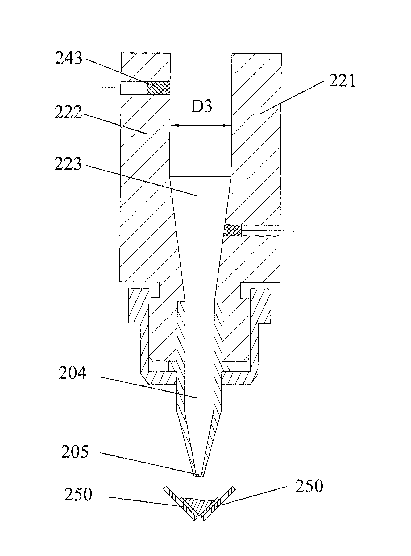
[0039]Referring to FIGS. 3-4, the apparatus 2 according to one embodiment of the present invention includes a nozzle device 20 for carrying out soldering process, a solder ball feeding device 21 for transferring a single solder ball to the nozzle device 20, a gas pump device 22 for supplying pressurized gases to the nozzle device 20, a laser device 23 for emitting laser beams to the solder ball and a control device 24 for controlling the sol...


PUM

PropertyMeasurementUnit
Pressureaaaaaaaaaa
Diameteraaaaaaaaaa
Distanceaaaaaaaaaa

Abstract

An apparatus for forming electrical solder connections in a disk drive unit includes: a nozzle device for carrying out soldering on two pre-welding surfaces; a solder ball feeding device for transferring a single solder ball to the nozzle device; a gas pump device for supplying pressurized gases to the nozzle device; a laser device for emitting laser beams to the solder ball,; and a control device including at least one sensor for at least detecting status of the solder ball or pressure in the nozzle device or distance between the nozzle device and the pre-welding surfaces, and a control unit connected with the at least one sensor. The present invention can easily control the solder ball, the pressurized gases and the laser beams, thereby keeping the pressure of the nozzle device and the laser energy stable and, in turn improving the soldering result.

Description

FIELD OF THE INVENTION[0001]The present invention relates to a soldering device and a soldering method and, more particularly, to an apparatus and a method for forming electrical solder connections in a disk drive unit.BACKGROUND OF THE INVENTION[0002]Hard disk drives are information storage devices that use thin film magnetic media to store data. Referring to FIG. 1a, a typical hard disk drive 1 in prior art comprises a head stack assembly (HSA) 10 with slider 11 (shown in FIG. 1b) thereon, a magnetic disk 12 mounted on a spindle motor 13 which causes the magnetic disk 12 to spin, and a motor base 14 to enclose the above-mentioned components.[0003]The slider 11 flies over the surface of the magnetic disk 12 at a high velocity to read data from or write data to concentric data tracks on the magnetic disk 12, which is positioned radially by a voice coil 15 embedded (e.g. by epoxy potting or overmolding) in a fantail spacer 16 of the HSA 10. Generally, a voice coil motor (VCM) 16 is u...

Claims


Application Information

Patent Timeline
IPC IPC(8): B23K1/005B23K26/12B23K26/02
CPCB23K1/0016B23K1/0056B23K3/0623B23K26/14B23K26/421B23K2201/42B23K26/1476B23K26/60B23K2101/42
Inventor LI, NINGZHAO, QIN PING
Owner SAE MAGNETICS (HK) LTD
Why Eureka
Try Eureka