
Device for fixing hydraulic pipe of boom swing type excavator

Inactive Publication Date: 2013-10-03
VOLVO CONSTR EQUIP
View PDF2 Cites 5 Cited by
  • Summary
  • Abstract
  • Description
  • Claims
  • Application Information

AI Technical Summary

Benefits of technology

The patent is about a hydraulic system for a work apparatus such as a boom cylinder. The technical effects of the patent are that it minimizes the length of the hydraulic pipe that runs from the control valve to the work apparatus, reducing abrasion and lifespan of the pipe. Additionally, the hydraulic pipe is not protruding outward from the boom cylinder or swing support, eliminating the need for a separate cover to protect the pipe and reducing manufacturing costs.

Problems solved by technology

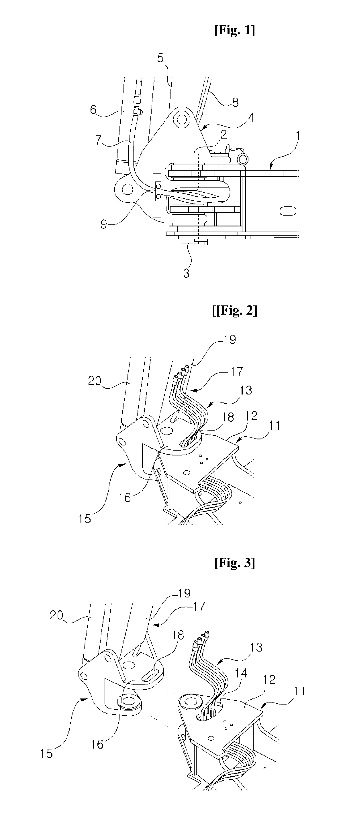
Thus, the conventional hydraulic pipe fixing device entails a problem in that when the work apparatus is pivotally rotated relative to the upper swing structure, the hydraulic pipes 7 and 8 are abraded due to an interference with other parts positioned at a connection portion of the upper swing structure 1 and the swing support 4, and a connection portion of the swing support 4 and the boom 5, thereby shortening the lifespan of the hydraulic pipes.

Method used


Image

  • Device for fixing hydraulic pipe of boom swing type excavator
  • Device for fixing hydraulic pipe of boom swing type excavator
  • Device for fixing hydraulic pipe of boom swing type excavator

Examples


first embodiment

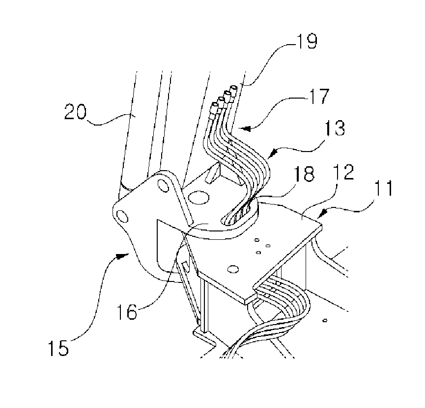
[0011]To accomplish the above object, in accordance with the present invention, there is provided a hydraulic pipe fixing device of a boom swing type excavator, which includes a swing support swingably connected to a front end portion of an upper swing structure, and a work apparatus rotatably fixed on the swing support, the hydraulic pipe fixing device including:[0012]a first hydraulic pipe support hole formed on an upper plate of the upper swing structure and configured to allow a hydraulic pipe 13 to pass therethrough from a control valve inside the upper swing structure, and[0013]a second hydraulic pipe support hole formed on an upper plate of the swing support at a position corresponding to the first hydraulic pipe support hole and configured to limit a horizontal movement of the hydraulic pipe and guide a vertical displacement of the hydraulic pipe when the work apparatus is pivotally rotated in a horizontal direction or shaken (or jerked) in a vertical direction relative to t...

second embodiment

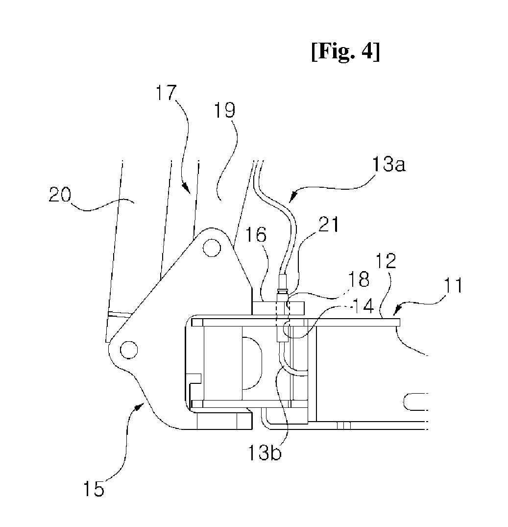
[0014]In accordance with the present invention, there is provided a hydraulic pipe fixing device of a boom swing type excavator, which includes a swing support swingably connected to a front end portion of an upper swing structure, and a work apparatus rotatably fixed on the swing support, the hydraulic pipe fixing device comprising:[0015]a first hydraulic pipe support hole formed on an upper plate of the swing support;[0016]a hydraulic pipe coupler fixedly mounted inside the first hydraulic pipe support hole;[0017]a second hydraulic pipe support hole formed on an upper plate of the upper swing structure at a position corresponding to the first hydraulic pipe support hole;[0018]a first hydraulic pipe having one end connected to the hydraulic pipe coupler and the other end connected to the work apparatus, the first hydraulic pipe being configured to be vertically moved according to a shaking or jerking movement of the work apparatus relative to the upper swing structure; and[0019]a s...


PUM


Abstract

A device for fixing a hydraulic pipe of a boom swing type excavator includes a swing support, which is connected to the front end of an upper swing body so as to swing, a working device, which is rotatably fixed to the swing support, a first hydraulic pipe supporting hole formed in a top plate of the upper swing member so that a hydraulic pipe passes therethrough from the control valve in the upper swing member, and a second hydraulic pipe supporting hole formed in a top plate of the swing support at a position corresponding to the first hydraulic pipe supporting hole, limiting the shaking of the hydraulic pipe in the right and left directions when the working device swings, and guiding displacement in the vertical direction.

Description

FIELD OF THE INVENTION[0001]The present invention relates to a hydraulic pipe fixing device of a boom swing type excavator on which a work apparatus is mounted so as to be swiveled horizontally with respect to an upper swing structure. More particularly, the present invention relates to such a hydraulic pipe fixing device of a boom swing type excavator that includes a swing support swingably connected to a front end portion of an upper swing structure, a work apparatus (including a boom, a boom cylinder and the like) rotatably fixed on the swing support, and a hydraulic pipe supplying a hydraulic fluid to the work apparatus.BACKGROUND OF THE INVENTION[0002]As shown in FIG. 1, a boom swing type excavator includes a swing support 4 swingably connected to a front end portion of an upper swing structure 1 by means of fixing pins 2 and 3, a swing cylinder (not shown) configured to horizontally swing the swing support 4 relative to the upper swing structure 1, a boom 54 fixed to an upper ...

Claims


Application Information

Patent Timeline
IPC IPC(8): E02F9/00F16L3/01
CPCE02F9/2275F16L3/01E02F9/00E02F3/384E02F3/42E02F9/14
Inventor HAN, YOUNG-GON
Owner VOLVO CONSTR EQUIP
Learn More