Systems and methods for constant voltage control and constant current control

a constant current and voltage control technology, applied in the field of integrated circuits, can solve the problems of reducing the efficiency of the power conversion system, reducing the actual length of the demagnetization process before the next switching cycle starts, and high cost, so as to reduce sampling errors and reduce power dissipation

Active Publication Date: 2013-10-03
ON BRIGHT ELECTRONICS SHANGHAI
View PDF8 Cites 93 Cited by
  • Summary
  • Abstract
  • Description
  • Claims
  • Application Information

AI Technical Summary

Benefits of technology

[0034]Many benefits are achieved by way of the present invention over conventional techniques. Certain embodiments of the present invention provide a system and method for charging a supply capacitor through a power switch during a start-up process using a large resistor to reduce power dissipation. Some embodiments of the present invention provide a system and method for demagnetization detection using a voltage at a switching node. Certain embodiments of the present invention provide a system and method for sampling a current sensing voltage in the middle of an on-time period to avoid sampling two separate voltage signals in order to reduce sampling errors. Some embodiments of the present invention provide a system and method for sampling a current sensing voltage in the middle of an on-time period (e.g., ½ Ton) to avoid an initial spike voltage problem when sampling the current sensing voltage at the beginning of the on-time period.

Problems solved by technology

To achieve good output current control, the power conversion system 100 often needs additional circuitry in the secondary side, which usually results in high cost.
Moreover, the required output current sensing resistor in the secondary side usually reduces the efficiency of the power conversion system 100.
Thus, the actual length of the demagnetization process before the next switching cycle starts is limited to the off-time period of the switch.
The power conversion system 200 often cannot achieve satisfactory dynamic responses with low standby power when the output load changes from no load to full load.

Method used


Image

  • Systems and methods for constant voltage control and constant current control
  • Systems and methods for constant voltage control and constant current control
  • Systems and methods for constant voltage control and constant current control

Examples


Embodiment Construction

[0052]The present invention is directed to integrated circuits. More particularly, the invention provides systems and methods for voltage regulation and current regulation. Merely by way of example, the invention has been applied to a power conversion system. But it would be recognized that the invention has a much broader range of applicability.

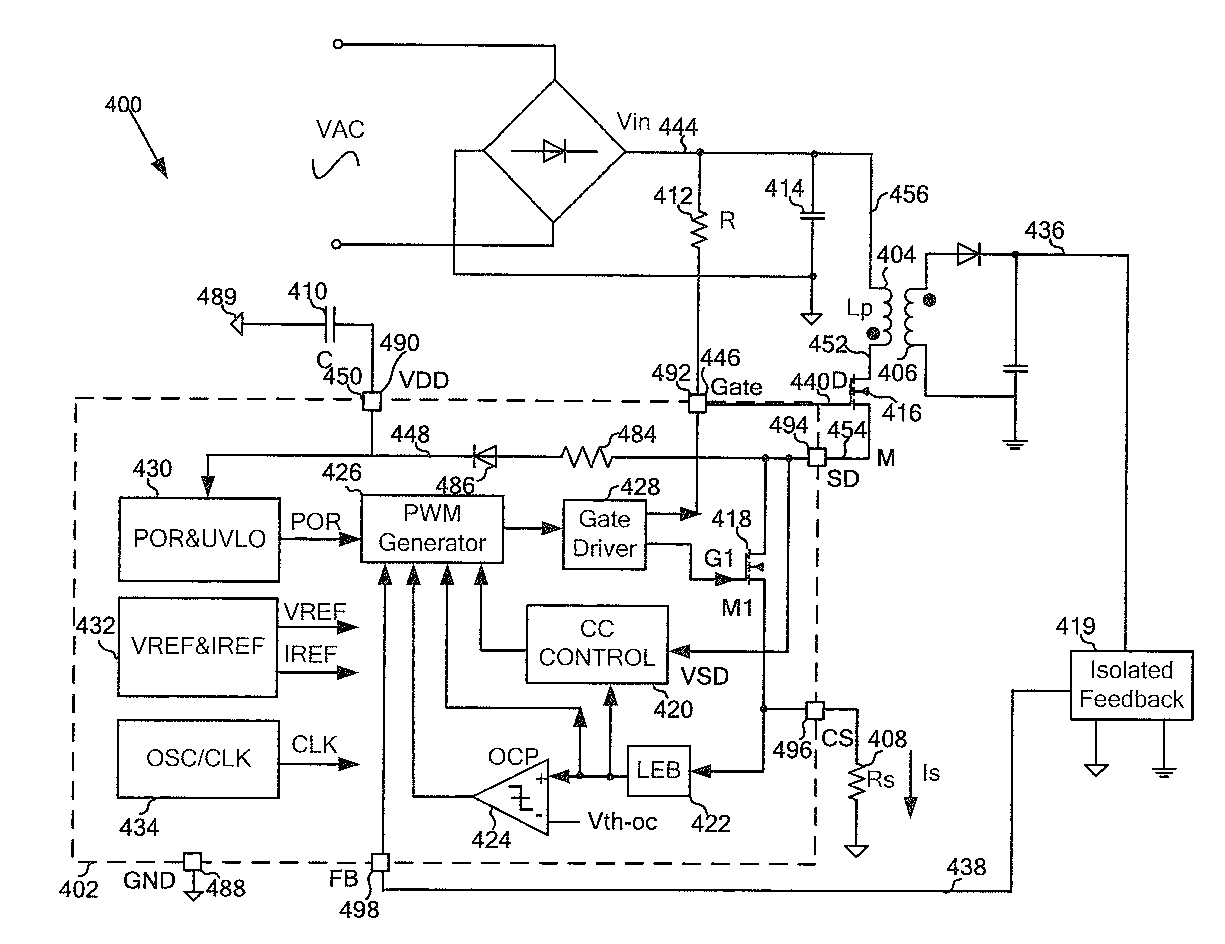
[0053]FIG. 4(a) is a simplified diagram showing a power conversion system with a controller according to an embodiment of the present invention. This diagram is merely an example, which should not unduly limit the scope of the claims. One of ordinary skill in the art would recognize many variations, alternatives, and modifications.

[0054]The power conversion system 400 includes a controller 402, a primary winding 404, a secondary winding 406, a current sensing resistor 408, an isolated feedback component 419, two capacitors 410 and 414, a resistor 412, and a power switch 416. The controller 402 includes a switch 418, a current-control compone...


PUM


Abstract

System and method for regulating a power conversion system. A system controller for regulating a power conversion system includes a first controller terminal, a second controller terminal and a third controller terminal. The system controller is configured to receive an input signal at the first controller terminal and turn on or off a switch based on at least information associated with the input signal to adjust a primary current flowing through a primary winding of the power conversion system, receive a first signal at the second controller terminal from the switch, and charge a capacitor through the third controller terminal in response to the first signal.

Description

1. CROSS-REFERENCES TO RELATED APPLICATIONS[0001]This application claims priority to Chinese Patent Application No. 201210099930.8, filed Mar. 31, 2012, incorporated by reference herein for all purposes.2. BACKGROUND OF THE INVENTION[0002]The present invention is directed to integrated circuits. More particularly, the invention provides systems and methods for voltage regulation and current regulation. Merely by way of example, the invention has been applied to a power conversion system. But it would be recognized that the invention has a much broader range of applicability.[0003]FIG. 1 is a simplified diagram showing a conventional flyback power conversion system. The power conversion system 100 includes a primary winding 110, a secondary winding 112, a power switch 120, a current sensing resistor 130, a rectifying diode 160, a capacitor 162, an isolated feedback component 114, and a controller 170. The controller 170 includes an under-voltage-lockout component 172, a pulse-width-m...

Claims


Application Information

Patent Timeline
Patent Type & Authority Applications(United States)
IPC IPC(8): H02M3/335
CPCH02M3/33515H02M3/33507H02M1/0003H02M3/33523
Inventor FANG, LIEYISUN, ZHIQIANG
Owner ON BRIGHT ELECTRONICS SHANGHAI
Why Eureka
Try Eureka