
Contour guided deformable image registration

a deformation image and contour technology, applied in the field of image processing, can solve the problems of uncontrollable sideways movement of voxels, the volume of tumors and surrounding anatomical structures to move and change, and the workload involved in adaptive re-planning can be complex and time-consuming

Active Publication Date: 2013-10-03
KONINKLIJKE PHILIPS ELECTRONICS NV
View PDF5 Cites 55 Cited by
  • Summary
  • Abstract
  • Description
  • Claims
  • Application Information

AI Technical Summary

Benefits of technology

The patent aims to solve issues related to high-speed data transfer. The technical effects include improvements in data transfer speed, reliability, and stability.

Problems solved by technology

Unfortunately, daily physiological changes (e.g., organ filling, weight loss, etc) can cause the tumor volume and surrounding anatomical structures to move and change in shape during the course of the therapy such that continuing to follow the initial plan may result in an actual received dose distribution the differs from the planned dose distribution.
Unfortunately, the workload involved in the such adaptive re-planning can be complex and time consuming as this involves delineation or segmentation of tissue of interest and anatomical structures from latest image data for the patient.
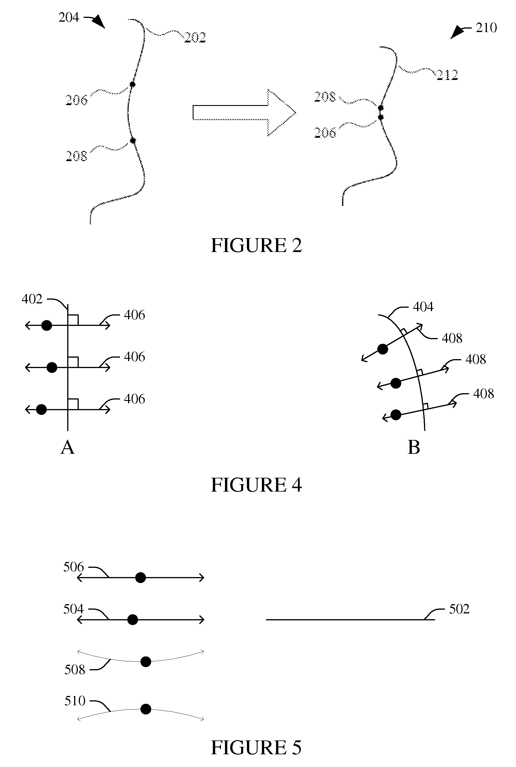
Unfortunately, with only the image gradient to guide the deformation process, as in the Demons deformable image registration, sideways movement of voxels is uncontrolled.
The direction of maximum steepness may not be the direction in which tissue actually moved, and (since it is computed by the noisy process of estimating a gradient, composed numerically approximated derivatives) may vary unsteadily.
This can lead to lack of smoothness and hence to geometric discontinuity in the deformed image and jaggedness in the propagated contours.

Method used


Image

  • Contour guided deformable image registration
  • Contour guided deformable image registration
  • Contour guided deformable image registration

Examples


Embodiment Construction

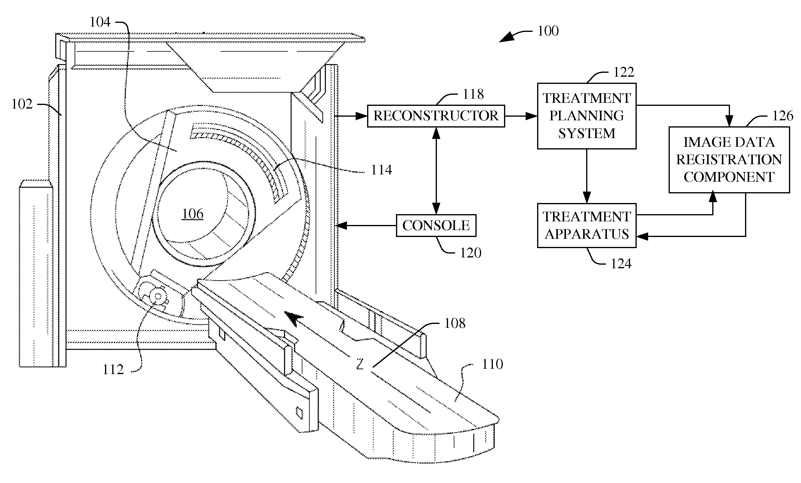
[0016]FIG. 1 schematically illustrates an imaging system such as a computed tomography (CT) scanner 100. The scanner 100 includes a stationary gantry 102 and a rotating gantry 104, which is rotatably supported by the stationary gantry 102. The rotating gantry 104 rotates around an examination region 106 about a longitudinal or z-axis 108 one or more times for one or more data acquisition cycles. A patient support 110, such as a couch, supports a patient in the examination region 106.

[0017]A radiation source 112, such as an X-ray tube, is supported by and rotates with the rotating gantry 104 around the examination region 106. The radiation source 112 emits radiation that is collimated by a source collimator to produce a generally fan, wedge, or cone shaped radiation beam that traverses the examination region 106. A radiation sensitive detector array 114 includes a one or two dimensional array of detector pixels that respectively detect radiation that traverses the examination region ...


PUM


Abstract

A method includes obtaining first volumetric image data, which is acquired at a first time, including a region of interest with a structural feature located at a first position. The method further includes obtaining second volumetric image data, which is acquired at a second different time, including the region of interest with the structural feature located at a second different position. The method further includes determining a registration transformation that registers the first and second volumetric image data such that the at least one structural feature in the first volumetric image data aligns with the at least one structural feature in the second volumetric image data. The registration transformation is based at least on a contour guided deformation registration. The method further includes generating a signal indicative of the registration transformation.

Description

FIELD OF THE INVENTION[0001]The following generally relates to image processing and more particular to contour guided deformable image registration, and is described with particular application to computed tomography (CT) and radiation therapy treatment planning; however, the following is also amenable to other imaging modalities, such a magnetic resonance imaging (MRI), positron emission tomography (PET), etc., and / or applications, and to other treatment modalities such as focussed ultrasound, interferential therapy, transcutaneous electrical nerve stimulation, pulsed shortwave therapy or laser therapy.BACKGROUND OF THE INVENTION[0002]Radiation treatment planning is the process creating a radiotherapy treatment plan for treating a tumor(s) via ionizing radiation. For treatment planning, the subject is scanned and the resulting volumetric image data is used as initial reference or planning image data to create a treatment plan for tumors or target volumes, segmented or contoured int...

Claims


Application Information

Patent Timeline
IPC IPC(8): G06T7/00
CPCG06T7/0024G06T7/0012G06T2207/10072G06T7/30
Inventor MALLYA, YOGISHPOSTON, TIMOTHY
Owner KONINKLIJKE PHILIPS ELECTRONICS NV
Learn More