
Varying transition zone manifold

a transition zone and manifold technology, applied in the field of slot die nozzles, can solve the problems of increasing the mass flow exchange rate at the expense of an increase in the manifold pressure drop, reducing the residence time across the manifold width, and reducing the efficiency of the manifold. the effect of reducing the stagnation

Active Publication Date: 2013-10-03
THE CLOEREN
View PDF2 Cites 12 Cited by
  • Summary
  • Abstract
  • Description
  • Claims
  • Application Information

AI Technical Summary

Benefits of technology

The present invention aims to improve extrusion apparatus by reducing transition stagnation and manifold residence time. It also aims to minimize differential clamshell defection across the flow channel width while reducing residence time in the transverse flow-providing manifold.

Problems solved by technology

Increasing the mass flow exchange rate comes at the opposing expense of an increase in the manifold pressure drop.
Transition stagnation is characterized by relatively low specific flow rates, or stagnant flow, and may result in deleterious time / temperature dependent polymer degradation.
Although this solution is beneficial within and proximate to the region of transverse flow initiation, this solution may be contrary to optimizing the mass flow exchange rate and minimizing the residence time across the manifold width, and in particular in a manifold end region.
As a result, degradation of a time / temperature-sensitive fluid mass can also result in a manifold end region.
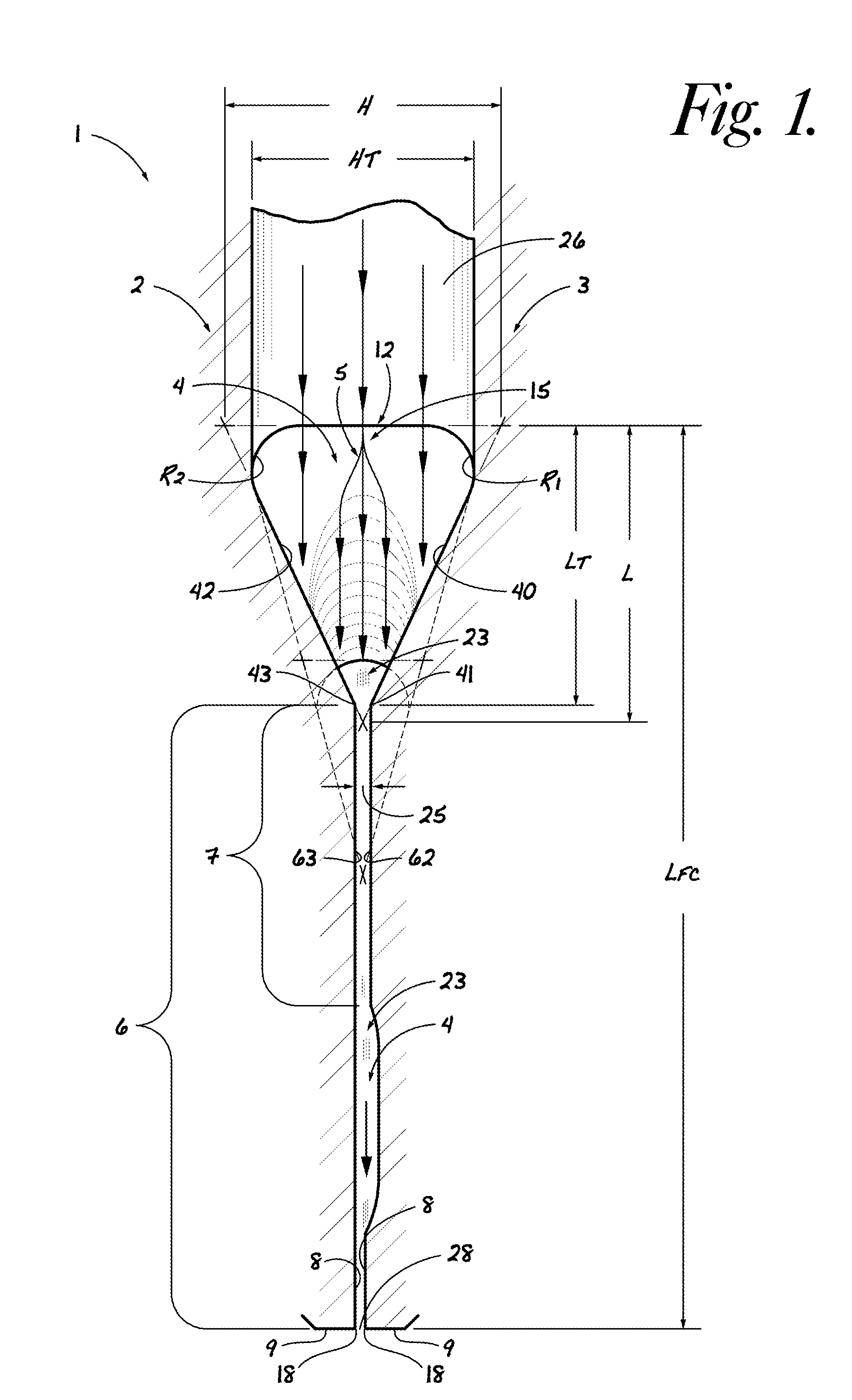
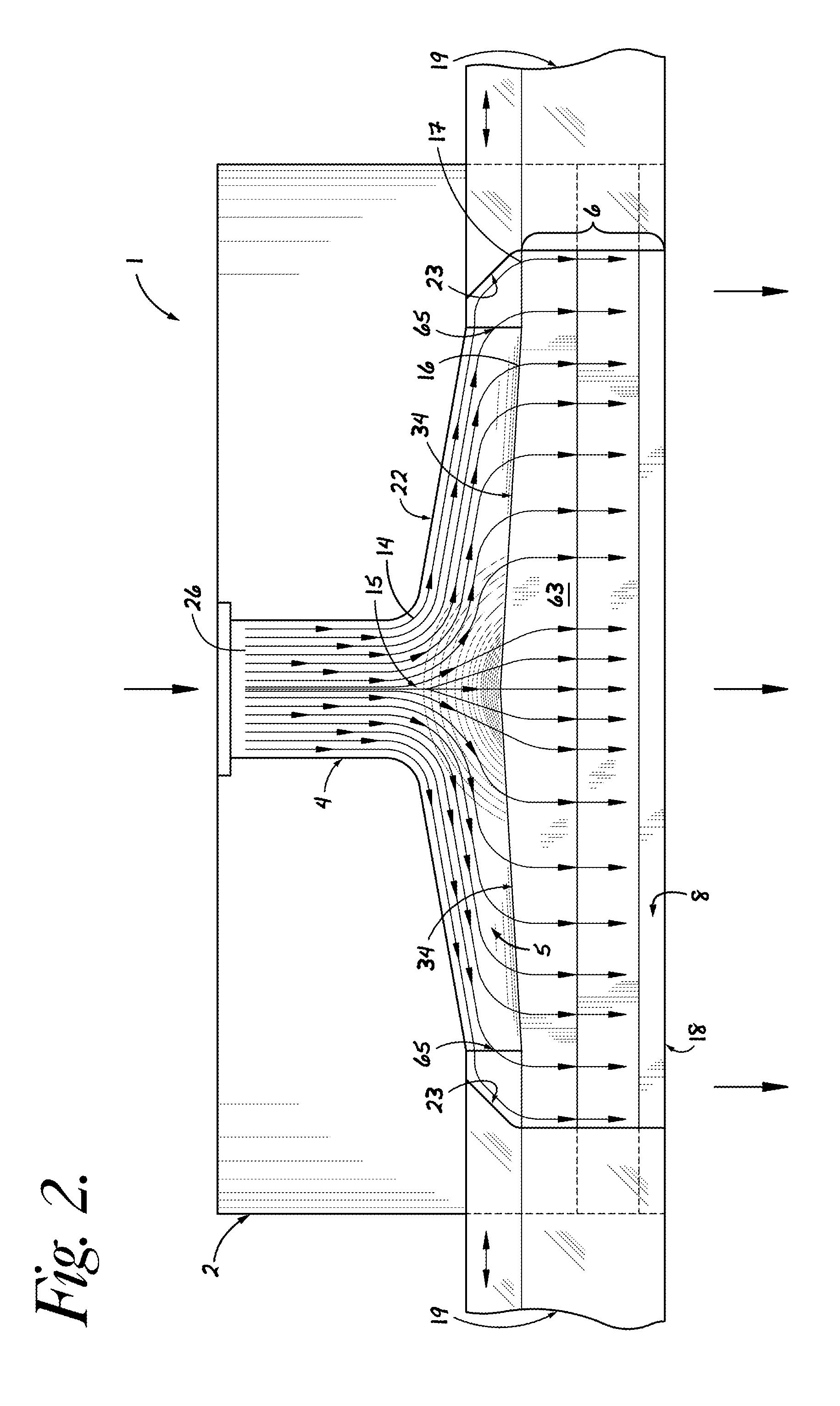
With continued reference to FIGS. 1 and 2, a further problem with minimizing the manifold cross-sectional area is an increase in flow resistance which results in an increase in the pressure differential from region 15 of transverse flow initiation to ends 20 of manifold 5.
Differential clamshell deflection of the unitary die structure negatively affects a prescribed mass flow distribution across the flow channel width.

Method used


Image

  • Varying transition zone manifold
  • Varying transition zone manifold
  • Varying transition zone manifold

Examples


first embodiment

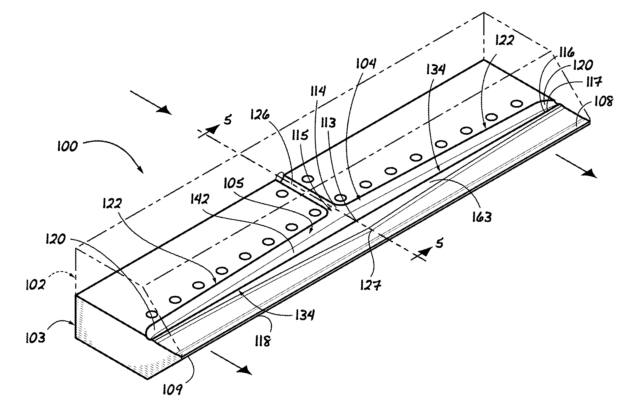
[0064]With reference to FIGS. 3 to 5, and to the invention, a description of an extrusion die 100 including a flow channel 104, is provided with reference to the description of die 1 as indicated by the use of corresponding numbers and alphabetical letters to designate like parts or features. For sake of brevity, therefore, details of die 100 that may be understood from the description of die 1, are generally not repeated. Unlike flow channel 4 of die 1, flow channel 104 of die 100 lacks a gull-wing portion convenient for receiving an internal deckle; however, die 100 may be modified in like manner, as may be understood from the description of the 6th embodiment of this invention.

[0065]Arrows located at the entrance to and exit from die 100, indicate the main direction of mass flow through the die beginning at an inlet 126 and ending at an exit orifice 128 of flow channel 104. Flow channel 104 further comprises a generally teardrop-shaped manifold 105, and a downstream flow channel ...

second embodiment

[0089]With reference to FIGS. 6 to 8, and to the invention, an abbreviated description of an extrusion die 200 including a flow channel 204, is provided with reference to the description of die 100 as indicated by the use of corresponding numbers and alphabetical letters to designate like parts or features. For sake of brevity, therefore, details of die 200 that may be understood from the description of die 100, are generally not repeated. Like flow channel 104 of die 100, flow channel 204 of die 200, as illustrated, lacks a gull-wing portion convenient for receiving an internal deckle; however, die 200 may be modified as may be understood from the description of the 6th embodiment of this invention.

[0090]Flow channel 204 includes a manifold 205, which extends transversely from the midline of the manifold width, and as indicated in FIG. 7, the manifold width may substantially correspond to width W of flow channel 204. Downstream flow channel portion 206 of flow channel 204 convenien...

third embodiment

[0109]With reference to FIGS. 9-11, and to the invention, an abbreviated description of an extrusion die 300 including a flow channel 304, is provided with reference to the description of die 100 as indicated by the use of corresponding numbers and alphabetical letters to designate like parts or features. For sake of brevity, therefore, details of die 300 that may be understood from the description of die 100, are generally not repeated. Like flow channel 104 of die 100, flow channel 304 of die 300, as illustrated, lacks a gull-wing portion convenient for receiving an internal deckle; however, die 300 may be modified as may be understood from the description of the 6th embodiment of this invention.

[0110]Flow channel 304 includes a manifold 305, which extends transversely from the midline of the manifold width, and as illustrated in FIG. 9, the manifold width may substantially correspond to width W of flow channel 304. Downstream flow channel portion 306 of flow channel 304 convenien...


PUM

PropertyMeasurementUnit
Lengthaaaaaaaaaa
Angleaaaaaaaaaa
Flow rateaaaaaaaaaa

Abstract

The present invention provides an extrusion die that includes a manifold transition zone that comprises a varying included angle. The varying included angle provides unparalleled freedom of design to achieve diverse fluid dynamic objectives, such as reduced residence time across the manifold width, reduced transition stagnation, improved streamlining of the mass flowing through the manifold, and reduced differential clamshell deflection across the flow channel width. The manifold may be transformed from one cross-sectional shape to another cross-sectional shape beneficially related to the varying included angle, including change from a generally extended cross-sectional shape to a generally teardrop-shaped cross-section. The manifold may include a first transition zone portion that includes the varying included angle, and a second transition zone portion that includes a constant included angle, and that is particularly beneficial for receiving an internal deckle.

Description

FIELD OF THE INVENTION[0001]This invention relates to a slot die nozzle for forming a flowing mass to a prescribed thickness and width, particularly useful for forming polymeric films, sheets and coatings.BACKGROUND OF THE INVENTION[0002]Conventional extrusion dies include multi-manifold and single-manifold flow channel designs, and are illustrated by end feed dies (U.S. Pat. No. 5,234,649 to Cloeren), T-Slot dies, coathanger dies, and multi-stage preland dies (U.S. Pat. Nos. 5,234,649 and 5,256,052 to Cloeren). The specific flow channel geometries are well described, and include a flow channel comprising a transverse flow-providing manifold spanning a width, and a downstream flow channel portion.[0003]The manifold may have a decreasing or constant cross-sectional area, and may have a variety of cross-sectional shapes, including a generally circular cross-section (U.S. Pat. No. 4,285,655 to Matsubara). Prior art FIG. 2 of Cloeren '649 illustrates a generally tear drop manifold shape...

Claims


Application Information

Patent Timeline
IPC IPC(8): B29C47/14B29C48/305B29C48/08B29C48/695
CPCB29C47/14B29C48/305B29C48/30B29C48/08B29C48/695
Inventor CLOEREN, PETER F.NEGRI, GIUSEPPECATHERINE, OLIVIER
Owner THE CLOEREN
Learn More