Golf club shaft and golf club

a golf club and shaft technology, applied in the field of golf club shafts, can solve the problems of deformation of the shaft, less power for players to swing golf clubs with such shafts, etc., and achieve the effect of low elastic modulus, easy deformation, and easy deformation

Inactive Publication Date: 2013-10-03
BRIDGESTONE SPORTS
View PDF9 Cites 4 Cited by
  • Summary
  • Abstract
  • Description
  • Claims
  • Application Information

AI Technical Summary

Benefits of technology

[0011]The purpose of the present invention is to provide a shaft in which carbon fibers having a low elastic modulus is arranged on its tip side and the tip side thereof having a high strength and a satisfactory appearance, and a golf club including the shaft.
[0029]According to the golf club shaft of this aspect, in which the diameter on the tip side is smaller than that on the butt side, low-elasticity carbon fibers are arranged on the butt side and high-elasticity carbon fibers are arranged on the tip side thereof, and thereby when an advanced player or the like who can hit the ball at a high head speed swings the golf club, the deformation of the shaft may not be concentrated on the tip side and the entire shaft is allowed to deform. With this configuration, great difference of the courses of the hit balls can be prevented regardless of any difference in the timings of swings, which results in stabilized courses of hit balls.

Problems solved by technology

In addition, if pitch-based carbon fibers having a fiber diameter larger than that of PAN-based carbon fibers are used, the surface of the fibers may become hairy when the shaft is ground to adjust the diameter of the shaft, which may result in degraded appearance of the shaft.
Therefore, it becomes less easy for a player of less power to swing a golf club with such a shaft.

Method used


Image

  • Golf club shaft and golf club
  • Golf club shaft and golf club
  • Golf club shaft and golf club

Examples


Embodiment Construction

[0034]Hereinbelow, an embodiment of a golf club shaft and a golf club according to the present invention will be described.

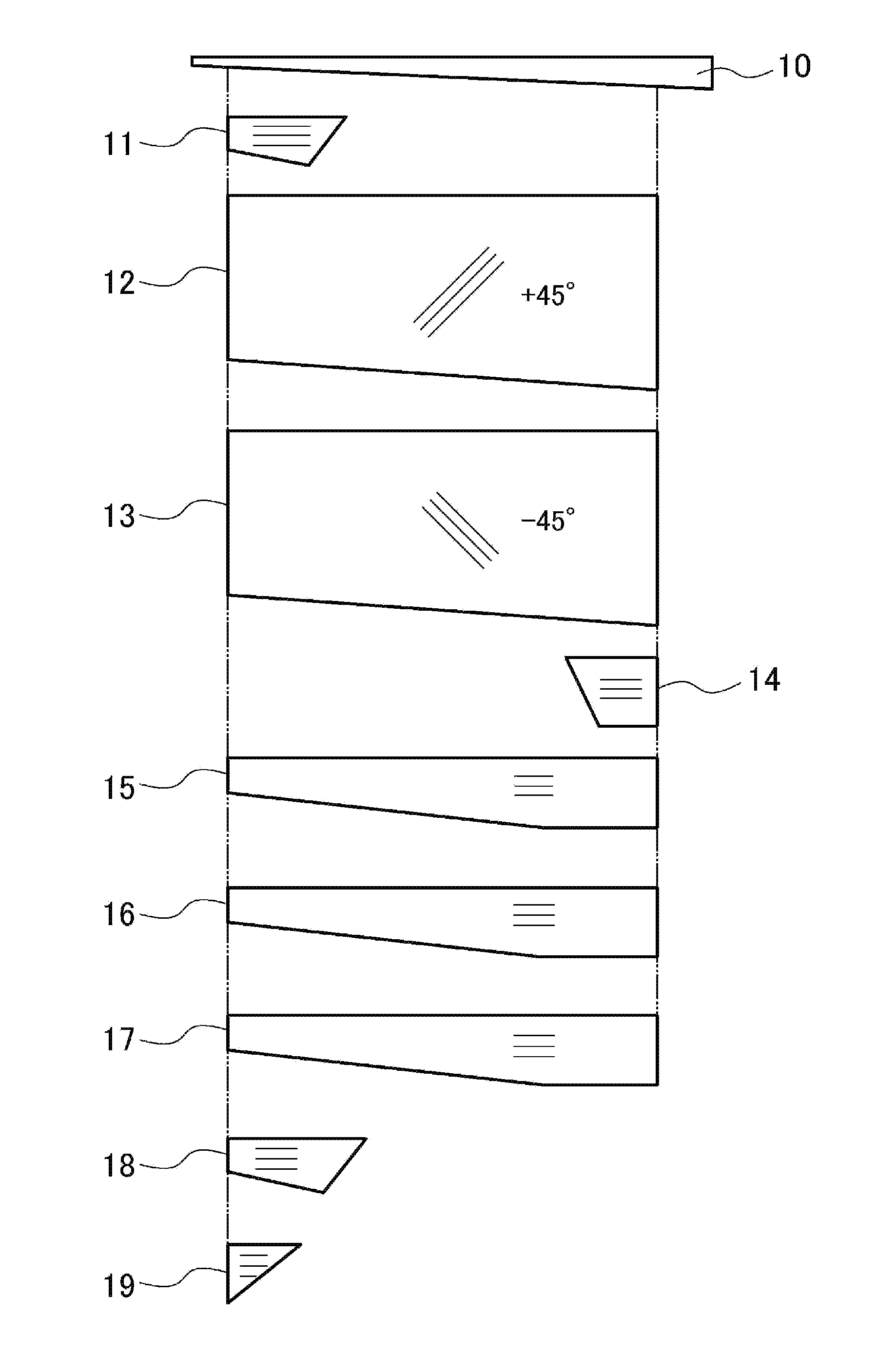
[0035]FIG. 1 is a development illustrating various types of prepregs for manufacturing an embodiment of the golf club shaft according to the present invention. In this manufacturing method, a mandrel 10 and prepregs 11 to 19 are used. The axial line of the mandrel 10 is a straight line. The shape of the cross section perpendicular to the shaft axial center line of the mandrel 10 is circular. The mandrel 10 includes a taper such that the tip side (head side) is narrow and the butt side (grip side) is thick. However, the mandrel 10 may include a portion having a regular diameter, which has a partially constant diameter.

[0036]Preferably, after applying a mold release agent on a surface of the mandrel 10, sheet-like prepregs 11 to 19 are serially wound.

[0037]The prepregs 11 to 19 include carbon fibers and a matrix resin. The carbon fiber for the prepreg 11 is a pitc...


PUM


Abstract

A golf club shaft is formed by curing wound fiber-containing prepregs and has a tip side and a butt side. In an embodiment, the prepregs include pitch-based carbon fiber-containing prepregs with a low elastic modulus, which are wound on the tip side, and polyacrylonitrile (PAN) based carbon fiber-containing prepregs, which are wound in an outermost layer on the tip side. In another embodiment, the prepregs include low-elasticity carbon fiber-containing prepregs wound on the tip side, and high-elasticity carbon fiber-containing prepregs wound on the butt side. In yet another embodiment, the prepregs include low-elasticity carbon-containing prepregs, which are wound on the butt side, and high elasticity carbon-containing prepregs, which are wound on the tip side.

Description

CROSS-REFERENCE TO RELATED APPLICATION[0001]This Application claims priorities from Japanese Patent Application No. 2012-075703 filed Mar. 29, 2012, Japanese Patent Application No. 2012-075704 filed Mar. 29, 2012, and Japanese Patent Application No. 2012-075705 filed Mar. 29, 2012, which are incorporated herein by reference in their entirety.BACKGROUND OF THE INVENTION[0002]The present invention relates to a golf club shaft, more particularly to a fiber reinforced resin-made golf club shaft, and to a golf club including the fiber reinforced resin-made golf club shaft.[0003]As shown in FIG. 2, a golf club 1 includes a shaft 3, which is mounted to a head 2. A grip 4 is provided on a trailing edge side (i.e., butt side) of the shaft 3. As shown in FIG. 3, in mounting the shaft 3 to the head 2, an epoxy-based adhesive 5 or the like is applied to a leading edge of the shaft 3, the shaft 3 is inserted into a hozel hole 6 of the head 2 and then the adhesive 5 is cured. FIGS. 2 and 3 illust...

Claims


Application Information

Patent Timeline
Patent Type & Authority Applications(United States)
IPC IPC(8): A63B53/10
CPCA63B53/10A63B53/145A63B2209/023A63B60/24A63B60/00
Inventor ITO, HIROMASA
Owner BRIDGESTONE SPORTS
Why Eureka
Try Eureka