Process for determining mobile water saturation in a reservoir formation

a reservoir formation and mobile water technology, applied in the direction of nuclear radiation detection, well-logging electric/magnetic detection, reradiation, etc., can solve the problems of uneconomical mining of these reserves using conventional techniques, disturb the in-situ conditions, and inaccessible resources, so as to facilitate direct determination of a first water volume and facilitate direct determination of a second water volume

Inactive Publication Date: 2013-10-03
SUNCOR ENERGY INC
View PDF10 Cites 18 Cited by
  • Summary
  • Abstract
  • Description
  • Claims
  • Application Information

AI Technical Summary

Benefits of technology

[0007]In accordance with one aspect of the invention there is provided a method for determining mobile water saturation in a reservoir having a borehole extending through the reservoir. The method involves obtaining first borehole data logs while the reservoir is subjected to first fluid conditions, the first borehole data logs including a first resistivity data log, and at least one data log that facilitates direct determination of a first water volume in the reservoir. The method also involves causing a mobile water displacement in the reservoir by changing the fluid conditions in the borehole to cause the reservoir to be subjec

Problems solved by technology

In some situations the resource is not economically accessible by direct mining of the surrounding formations.
Such resources are often in a fluid state and are trapped in a reservoir formed by the surrounding reservoir formation.
Viscous hydrocarbons or bitumen may be located in rock or sand deposits well below the surface of the earth, making mining of these reserves using conventional techniques uneconomical.
Steam assisted gravity drainage (SAGD) techniques may be employed to access such reserves, but due to the high capital cost and the relatively large energy cost associated with extracting the hydrocarbons,

Method used


Image

  • Process for determining mobile water saturation in a reservoir formation
  • Process for determining mobile water saturation in a reservoir formation
  • Process for determining mobile water saturation in a reservoir formation

Examples


Embodiment Construction

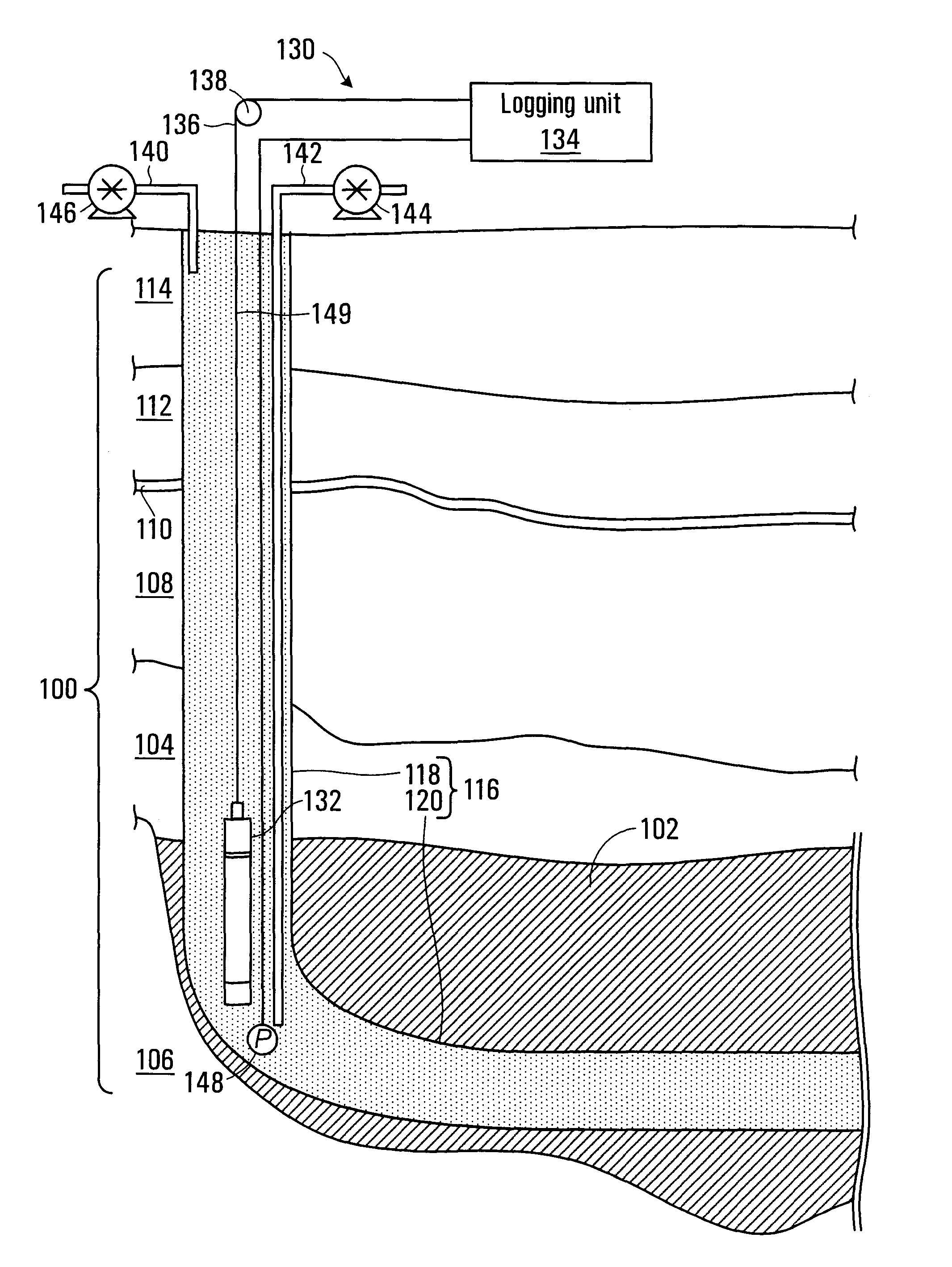
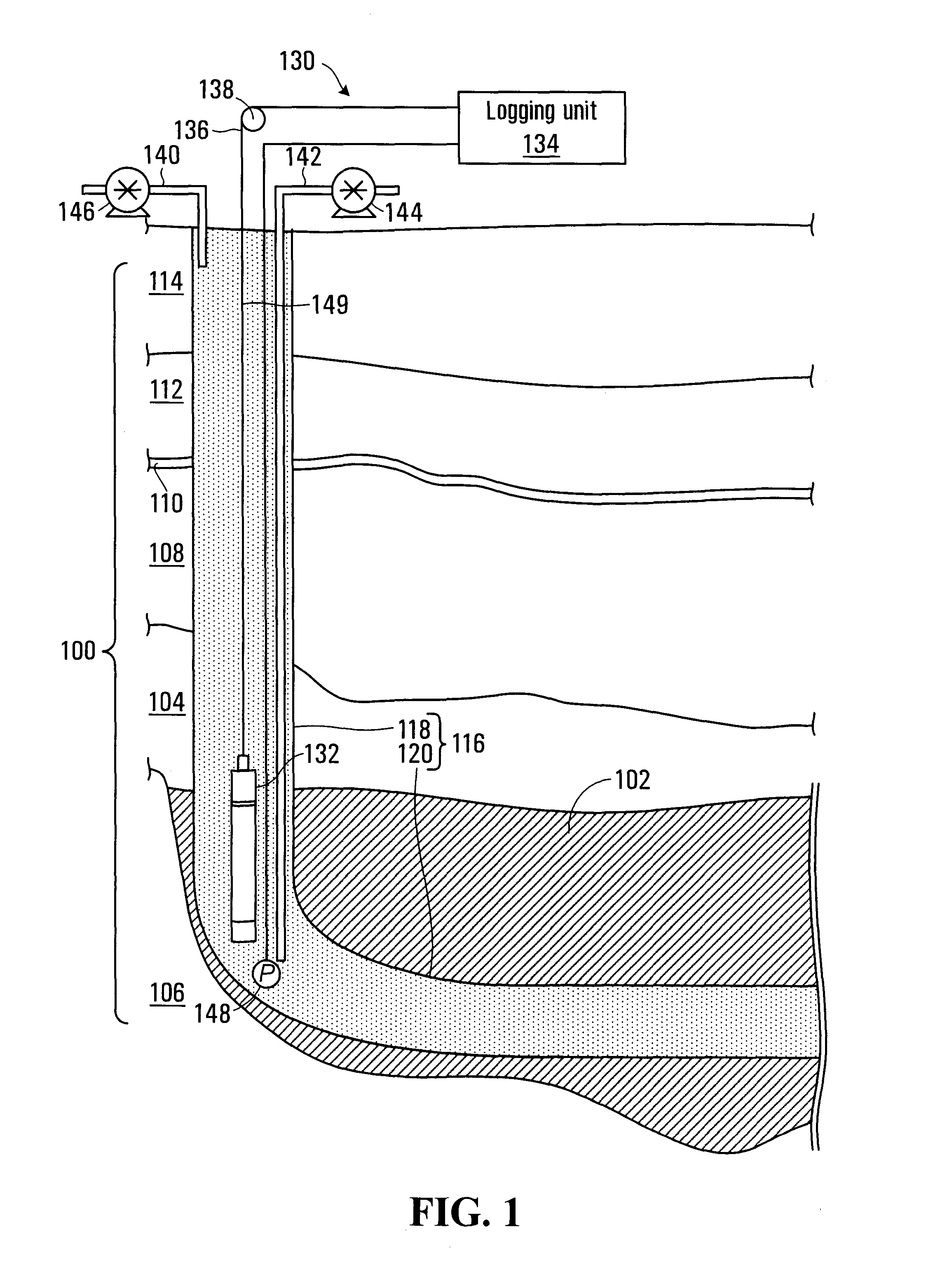
[0075]Referring to FIG. 1, an exemplary reservoir formation is shown at 100. In the embodiment shown the formation 100 includes a permeable layer 104, an underlying less permeable or impermeable rock layer 106, and several other rock layers 108-114 overlying the permeable layer 104. The permeable layer 104 includes pores that facilitate accumulation of fluids, which are trapped by the underlying layer 106 to define a reservoir 102 within the permeable layer 104. Fluids trapped in the reservoir 102 may include fluids such as hydrocarbons and water, for example. In the embodiment shown in FIG. 1, the reservoir 102 only occupies a portion of the permeable layer 104, although in other embodiments the reservoir may extend substantially throughout the permeable layer. In one embodiment the permeable layer 104 may comprise a porous rock formation. In other embodiments the permeable layer 104 may comprise sand particles having interstitial spaces in-between particles that act as pores for c...


PUM


Abstract

A method for determining mobile water saturation in a reservoir having a borehole extending through the reservoir is disclosed. The method involves obtaining a first borehole data log while the reservoir is subjected to first fluid conditions, and causing a mobile water displacement in the reservoir by changing the fluid conditions in the borehole to cause the reservoir to be subjected to second fluid conditions, the second fluid conditions differing from the first fluid conditions. The method further involves obtaining a second borehole data log under the second fluid conditions, and estimating the mobile water displacement using the first and second data logs, the estimated mobile water displacement providing an estimate of the mobile water saturation in the reservoir.

Description

BACKGROUND OF THE INVENTION[0001]1. Field of Invention[0002]This invention relates generally to determining mobile water saturation in a reservoir formation.[0003]2. Description of Related Art[0004]Resources often reside in reservoirs below the surface of the earth. In some situations the resource is not economically accessible by direct mining of the surrounding formations. Alternative methods may be employed to access and extract the resources, such as hydrocarbons, water, or other minerals. Such resources are often in a fluid state and are trapped in a reservoir formed by the surrounding reservoir formation. Examples of such resources are ground water reservoirs, liquid hydrocarbon, and gaseous hydrocarbon reserves.[0005]Viscous hydrocarbons or bitumen may be located in rock or sand deposits well below the surface of the earth, making mining of these reserves using conventional techniques uneconomical. Steam assisted gravity drainage (SAGD) techniques may be employed to access su...

Claims


Application Information

Patent Timeline
IPC IPC(8): G01V9/02G01V5/04G01V3/34
CPCE21B49/00G01V9/02G01V5/045G01V3/34
Inventor AL ADANI, NABIL
Owner SUNCOR ENERGY INC
Why Eureka
Try Eureka