Accelerated bench-testing of medical devices

Inactive Publication Date: 2013-10-03
ENDOSPAN
View PDF20 Cites 15 Cited by
  • Summary
  • Abstract
  • Description
  • Claims
  • Application Information

AI Technical Summary

Benefits of technology

[0005]For some applications, in order to effect the periodic increases and decreases in pressure, the tester comprises a first interface surface that is shaped so as to define one or more apertures, and a second interface surface that is shaped so as to define one or more ports. A motor of the tester effects relative translation between the first and second interface surfaces, thereby effecting a time-varying overlap between at a least a subgroup of the apertures and at least a subgroup of the ports. Whenever one of the apertures overlaps a given port, fluid flows through the aperture into the port. Whenever none of the apertures overlaps a given port, the first interface surface blocks fluid flow into the port.
[0006]For some applications, the tester comprises a fluid control assembly; one or more fixtures, configured to allow disposition therewithin of respective ones of the medical devices; and a fluid pump. The fluid control assembly comprises a fluid-control container, a fluid controller, an

Problems solved by technology

Because implanted vascular prostheses are subjected to continuous changes in blood pressure and other physiological stresses, they must be fatigue-te

Method used


Image

  • Accelerated bench-testing of medical devices
  • Accelerated bench-testing of medical devices
  • Accelerated bench-testing of medical devices

Examples


Embodiment Construction

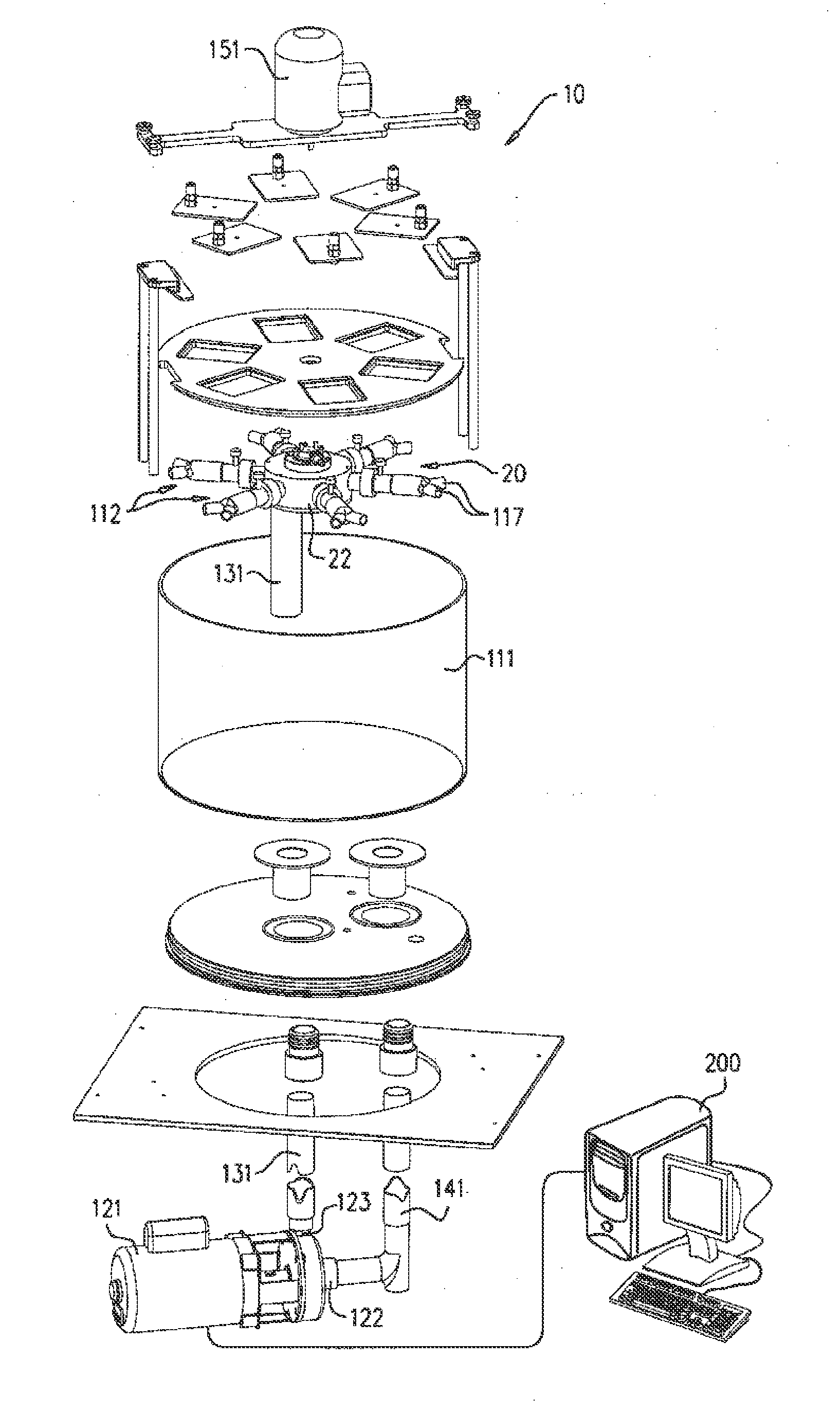
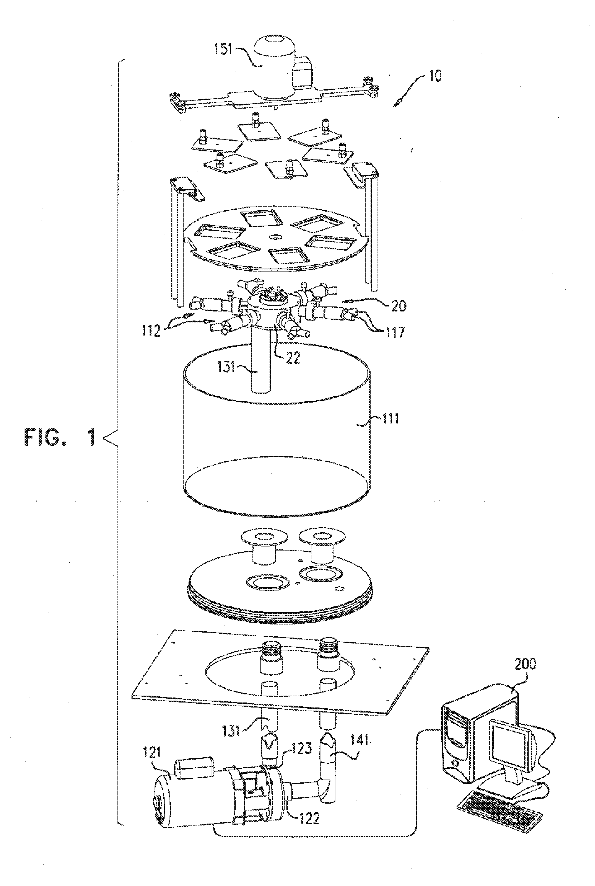
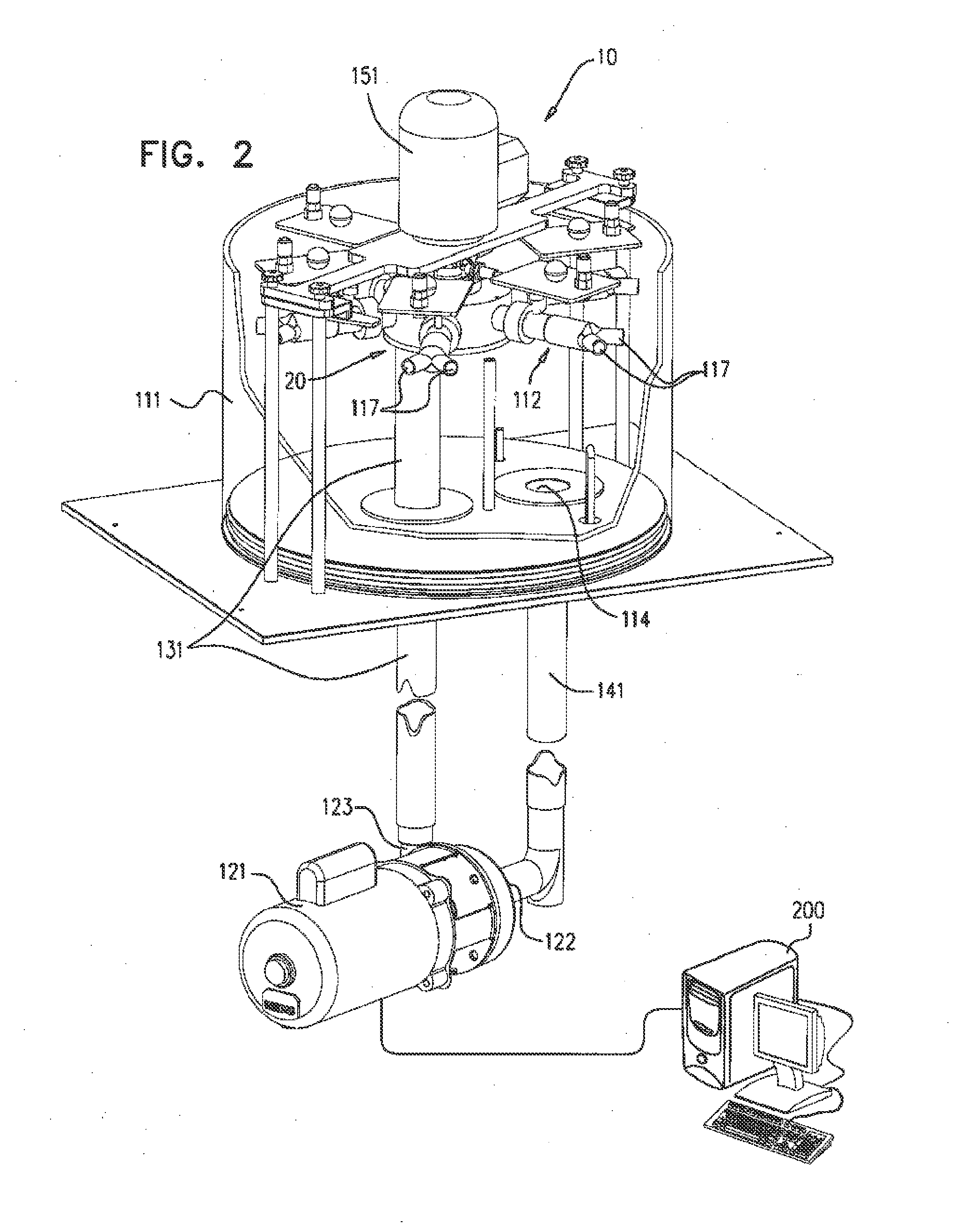
[0084]FIGS. 1 and 2 are schematic illustrations of a biomedical tester 10 for fatigue testing one or more medical devices, in accordance with an application of the present invention. FIG. 1 shows unassembled components of tester 10, while FIG. 2 shows the assembled tester. Tester 10 typically comprises a fluid control assembly 20, which helps control the flow of fluid through the tester, and one or more fixtures 112, which are configured to allow disposition therewithin of respective ones of the medical devices. Fluid control assembly comprises a motor 151. The motor need not operate in a pulsatile regimen, as is necessary in some commercially-available testers, and thus may be able to operate at a higher frequency than some commercially-available testers.

[0085]The tester cyclically increases and decreases the pressure of a fluid within fixtures 112 in contact with the medical devices, during a plurality of cycles, in order to simulate the pulsatile pressure within human blood vesse...


PUM


Abstract

A biomedical tester includes a fluid-control container, shaped to define a fluid-control container port and a first interface surface defining fluid-control container apertures. A fluid controller is shaped to define a second interface surface defining controller ports. These elements and a motor are arranged to relative translation between the first and second interface surfaces; thereby effecting a time-varying overlap between subgroups of the system. Fixtures allow disposition therewithin of respective medical devices. Each of the fixtures includes one or more fixture first ports and fixture second ports. The fixture first ports are mounted in fluid Communication respective with the controller ports. A fluid pump includes first and second pump ports in fluid communication with the fixture second ports and the fluid-control container port, respectively.

Description

CROSS-REFERENCE TO RELATED APPLICATIONS[0001]The present application claims priority from U.S. Provisional Application 61 / 392,059, filed Oct. 12, 2010, which is assigned to the assignee of the present application and is incorporated herein by reference.FIELD OF THE APPLICATION[0002]The present invention relates generally to apparatus and methods for fatigue testing, and specifically to apparatus and methods for accelerated fatigue testing of implantable medical devices.BACKGROUND OF THE INVENTION[0003]Vascular prostheses, such as stents, grafts, and stent-grafts, are used for repairing vascular abnormalities, such as abdominal aortic aneurysm (AAA). Because implanted vascular prostheses are subjected to continuous changes in blood pressure and other physiological stresses, they must be fatigue-tested during product development and regulatory approval processes. Commercially-available fatigue test instruments generally offer accelerated testing using standing pressure waves acting on...

Claims


Application Information

Patent Timeline
IPC IPC(8): G01F17/00
CPCG01M99/007G01F17/00G01N3/32A61F2/2472A61F2240/008
Inventor RAZ, SAGIBENARY, RAPHAELSHALEV, ALON
Owner ENDOSPAN
Why Eureka
Try Eureka