Unlock instant, AI-driven research and patent intelligence for your innovation.

Arrangement For And Method Of Gasifying Solid Fuel

a gasification and solid fuel technology, applied in the details of gasification processes, gas purification by non-gaseous materials condensation, combustion treatment, etc., can solve the problems of complicated gasification process, complicated further use of gas, and complicated gasification process

Active Publication Date: 2013-10-10
AMEC FOSTER WHEELER ENERGIA
View PDF13 Cites 0 Cited by
  • Summary
  • Abstract
  • Description
  • Claims
  • Application Information

AI Technical Summary

Benefits of technology

The invention provides an arrangement and method for gasifying solid fuel without the need for additional catalysts, which makes the process more reliable. The arrangement can also effectively cool down and remove sticky and melt components produced during thermal cracking, while minimizing the risk of clogging the cooler. Additionally, the arrangement is energy efficient and allows for a reliable cooling and change of sticky components to non-sticky ones before their removal from the cooler.

Problems solved by technology

This complicates the recovery of heat from the gases or cooling the gas.
Problems also appear in the gasification processes because of the substances mat stick on heat exchange surfaces.
Especially, with the gasification gases derived from biofuels, heat recovery and also, possibly, further use of the gas are substantially complicated by components that are contained in the biofuels and have a tendency to stick on, for example, the heat exchange surfaces.
Since the particle filters that filter the gas at a high temperature are expensive and are prone to being damaged, the product gas is generally cooled prior to the filtering.
Especially, when gasifying waste materials and biomass, considerable amounts of tar compounds can be generated.
Thus, tar compounds, for example, reduce the heat exchange efficiency of the heat exchange surfaces, weakening the operation of the equipment and clogging the filtering elements of the filter, thereby, increasing die pressure loss.
This causes cracking of tar compounds.
Thus, the solution is especially prone to clogging of the heat surfaces downstream of the reforming unit.

Method used


Image

  • Arrangement For And Method Of Gasifying Solid Fuel
  • Arrangement For And Method Of Gasifying Solid Fuel

Examples


Embodiment Construction

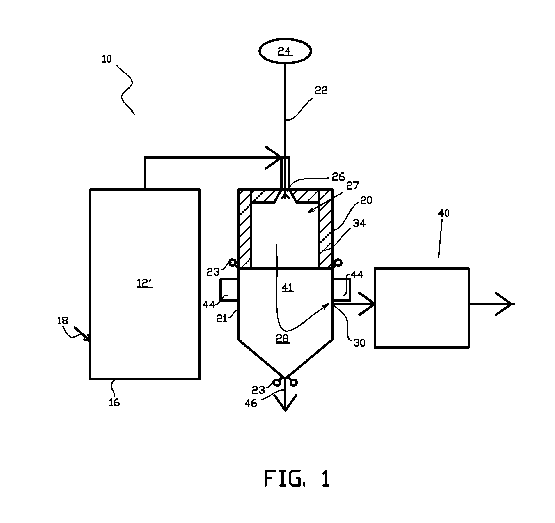
[0029]FIG. 1 shows an embodiment in accordance with die invention of an arrangement 10 for gasifying solid fuel. The embodiment of FIG. 1 comprises a gasification reactor 12′, in which fuel is gasified in such a way that the product gas generated can be further oxidized. The arrangement also comprises a gas treatment reactor 20 arranged in a flow direction of the product gas, in gas flow connection with the gasification reactor 12′ for thermal cracking of the product gas, and a radiation heat exchange cooler 41 of gas arranged in connection with the gas treatment reactor. This entity provides an arrangement for generating oxidizable product gas from solid fuel, by means of which arrangement, good quality product gas can he generated in a reliable manner by utilizing thermal cracking and, at the same time, taking care of the melt components generated in the thermal cracking in an operationally reliable manner by solidifying them to a non-sticky form and by treating them in a non-stic...


PUM

PropertyMeasurementUnit
temperatureaaaaaaaaaa

Abstract

An arrangement for gasifying solid fuel includes a gasification reactor for producing further oxidizable product gas from solid fuel and a gas treatment reactor arranged in a flow direction of the product gas in gas flow connection with the gasification reactor. The gas treatment reactor includes a supply for supplying oxygenous gas to the gas treatment reactor for partial oxidization of product gas and for thermal cracking thereof A radiation heat exchange cooler for cooling the product gas is arranged in connection with the gas treatment reactor to solidify melt components in the product gas. A discharge connection is arranged in the lower portion of the radiation heat exchange cooler for removing solidified melt components from the radiation heat exchange cooler. A method of gasifying solid fuel in a gasification reactor is also presented.

Description

[0001]This application is a U.S. national stage application of PCX International Application No. PCT / FI2011 / 051135, filed Dec. 19, 2011, published as International Publication No. WO 2012 / 085345 A1, and which claims priority from Finnish patent application number 20106344, filed Dec. 20, 2010.FIELD OF THE INVENTION[0002]The present invention relates to an arrangement for gasifying solid fuel.[0003]The invention also relates to a method of gasifying solid fuel.BACKGROUND OF THE INVENTION[0004]Hot gases treated in certain industrial processes contain components that have a tendency to stick on, for example, heat exchange surfaces. Sticky compounds may also be generated as a result of cooling. This complicates the recovery of heat from the gases or cooling the gas.[0005]Problems also appear in the gasification processes because of the substances mat stick on heat exchange surfaces. Gasification or combustion of solid carbonaceous material in a circulating fluidized bed reactor, in whic...

Claims


Application Information

Patent Timeline
Patent Type & Authority Applications(United States)
IPC IPC(8): C10J3/72
CPCC10J3/56F28D2021/0075C10J3/86C10J2300/0916C10K1/046C10J3/72C10K3/005F23G5/0276F23G5/30F23G2201/301F23G2201/40F23G2203/501F28D13/00C10J2300/1884C10J3/84C10B47/24C10K1/04F23G5/027F23J3/00F28D1/00
Inventor BERG, EERO
Owner AMEC FOSTER WHEELER ENERGIA