Reverse heterojunctions for solar cells

a solar cell and heterojunction technology, applied in the field of photovoltaic solar cells, can solve the problems of reducing the diffusion length of minority carriers, the design of three junction solar cells is rapidly approaching the practical efficiency limit, etc., and achieves the effect of reducing the sheet resistance of emitters, increasing subcell current, and minimal effect on open-circuit voltag

Active Publication Date: 2013-10-10
CACTUS MATERIALS INC
View PDF1 Cites 26 Cited by
  • Summary
  • Abstract
  • Description
  • Claims
  • Application Information

AI Technical Summary

Benefits of technology

[0016]According to the invention, in a multijunction solar cell, at least one subcell is provided with a reverse heterojunction, the reverse heterojunction being formed with an emitter and an adjacent base, wherein the emitter has a band gap that is at least 10 meV lower than that of the adjacent base in order to reduce the sheet resistance of the emitter and / or to increase the subcell current with minimal effect on the open-circuit voltage. In another embodiment of the invention, a single junction solar cell is provided with a reverse heterojunction formed with the emitter and the base, wherein the emitter has a band gap that is at least 10 meV lower than that of the adjacent base in order to reduce sheet resistance of the emitter and / or to increase the short-circuit current with minimal effect on the open-circuit voltage. Because of the increase in current, the decrease in emitter sheet resistance, and relatively unchanged open-circuit voltage of the subcell, the efficiency of a solar cell employing one or more subcells with reverse heterojunctions is enhanced.

Problems solved by technology

Designs for three junction solar cells are rapidly approaching their practical efficiency limits.
However, typical strategies for reducing emitter sheet resistance involve corresponding losses in short-circuit current, such as increasing the emitter doping level, which decreases the minority carrier diffusion length.

Method used


Image

  • Reverse heterojunctions for solar cells
  • Reverse heterojunctions for solar cells
  • Reverse heterojunctions for solar cells

Examples


Embodiment Construction

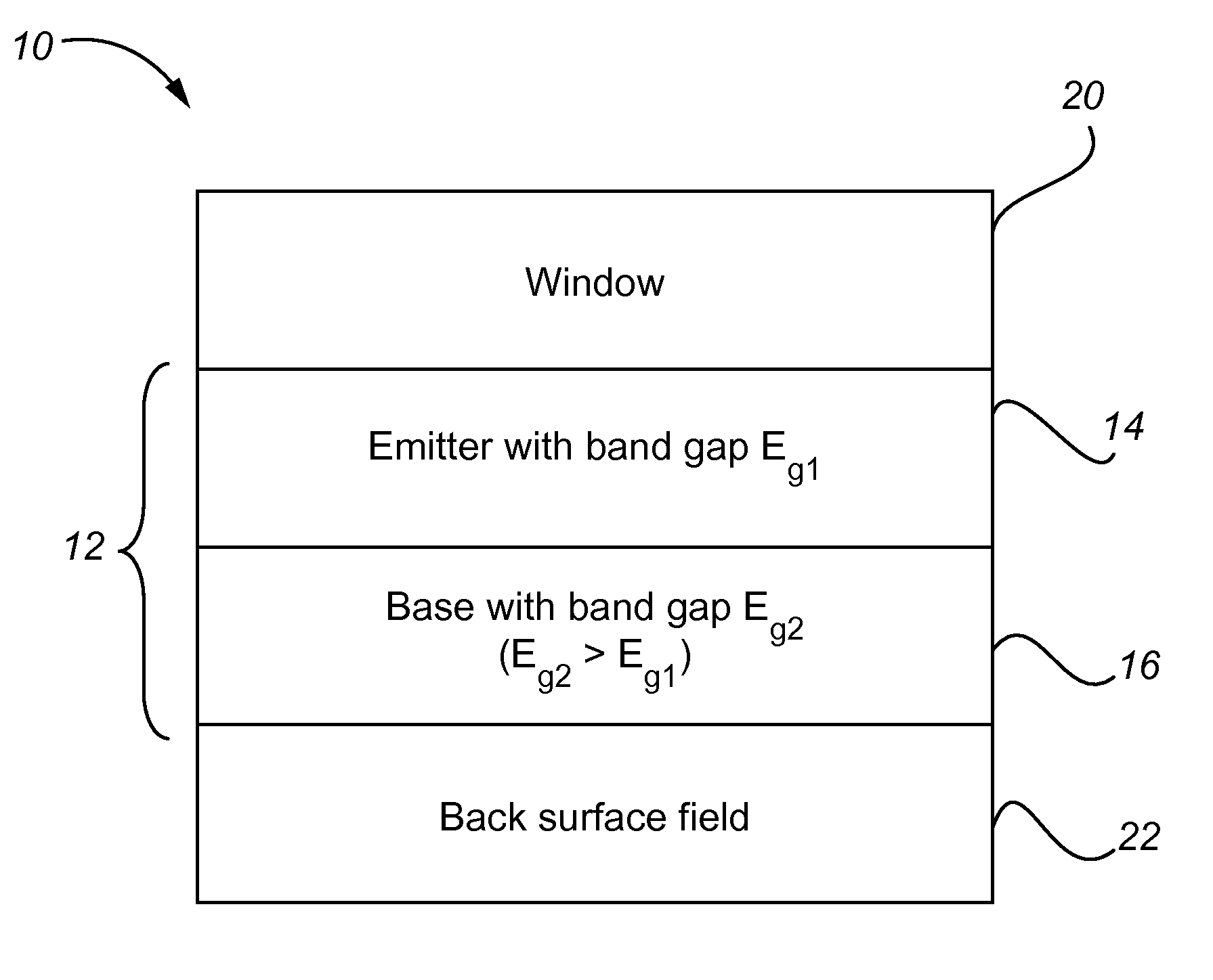
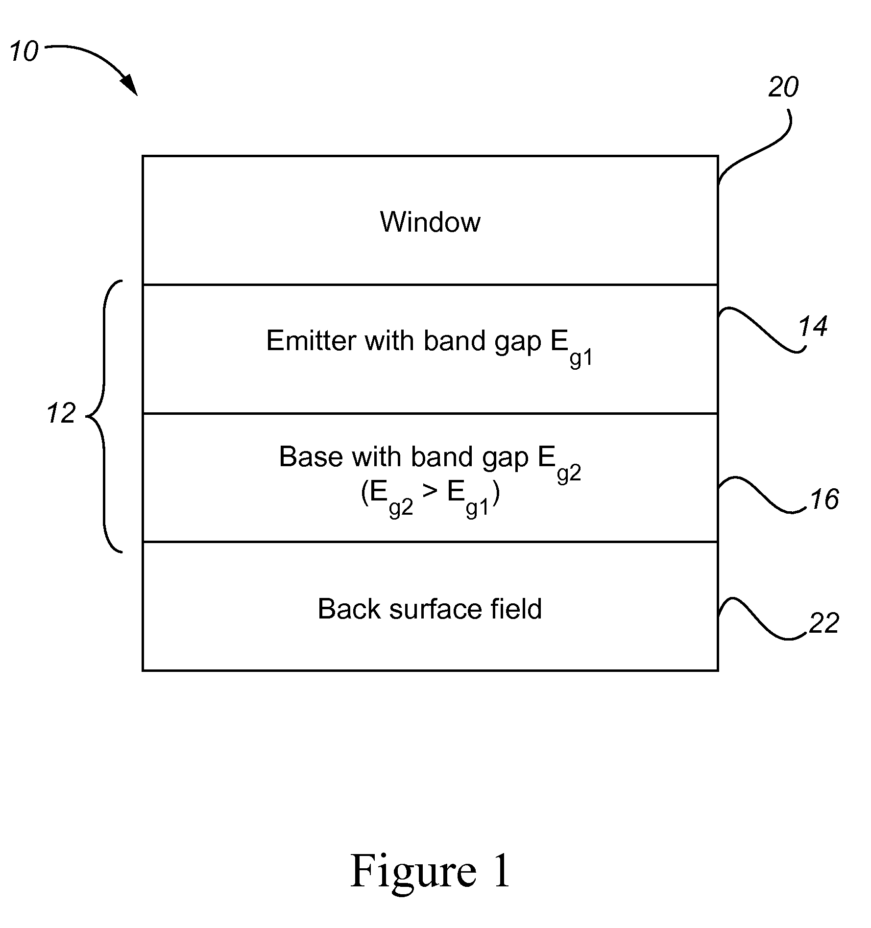
[0024]The invention discloses a reverse heterojunction for use as an emitter-base pair in a solar cell. In one embodiment as shown in FIG. 1, a reverse heterojunction 12 comprises an emitter 14 and base 16 of a subcell 10 of a solar cell with one or more subcells. This subcell 10 includes a window 20 and includes a back surface field 22. In one preferred embodiment, this subcell 10 is the top subcell of a solar cell. The disclosed heterojunction is named a “reverse heterojunction” because it comprises an emitter and base where the band gap of the emitter (Eg1) is at least 10 meV lower than the band gap of the base (Eg2), and preferably not more than 150 meV lower than the band gap of the base. This is counter to the teaching of the prior art, which specifies that the emitter should have the same band gap as the base, as in a homojunction design, or a higher band gap than that of the base. The particular design having an emitter with a higher band gap than that of the base is a heter...


PUM


Abstract

In a solar cell having one or more subcells, at least one subcell is provided with a reverse heterojunction, the reverse heterojunction being formed with an emitter and an adjacent base, wherein the emitter has a band gap that is at least 10 meV lower than that of the adjacent base in order to reduce sheet resistance of the emitter and / or increase the subcell current with minimal effect on the open-circuit voltage. Because of the increase in current, the decrease in emitter sheet resistance, and relatively unchanged open-circuit voltage of the subcell, the efficiency of a solar cell employing one or more subcells with reverse heterojunctions is enhanced.

Description

CROSS-REFERENCES TO RELATED APPLICATIONS[0001]NOT APPLICABLESTATEMENT AS TO RIGHTS TO INVENTIONS MADE UNDER FEDERALLY SPONSORED RESEARCH OR DEVELOPMENT[0002]NOT APPLICABLEREFERENCE TO A “SEQUENCE LISTING,” A TABLE, OR A COMPUTER PROGRAM LISTING APPENDIX SUBMITTED ON A COMPACT DISK[0003]NOT APPLICABLEBACKGROUND OF THE INVENTION[0004]1. Field of Invention[0005]The invention generally relates to photovoltaic solar cells and, more particularly, to high-efficiency photovoltaic solar cells based on III-V semiconductor compounds.[0006]2. Description of Related Art[0007]Solar cells based on III-V semiconductor compounds have demonstrated high efficiencies for the generation of electricity from solar radiation. Known single junction solar cells formed primarily of III-V materials have reached efficiencies up to 28.3% at 1 sun solar intensity. Known multijunction III-V solar cells have reached 36.9% efficiency at 1 sun and 43.5% under concentrated sunlight equivalent to several hundred suns (...

Claims


Application Information

Patent Timeline
Patent Type & Authority Applications(United States)
IPC IPC(8): H01L31/0264H01L31/18
CPCH01L31/0725Y02E10/544H01L31/0735
Inventor JONES-ALBERTUS, REBECCA E.SHELDON, MICHAEL J.
Owner CACTUS MATERIALS INC
Why Eureka
Try Eureka