Syringe Filter

a filtration device and syringe technology, applied in the direction of filtration separation, membranes, separation processes, etc., can solve the problems of high scrap rate, labor-intensive inspection process, inconsistent product appearance,

Active Publication Date: 2013-10-10
NAT SCI
View PDF5 Cites 37 Cited by
  • Summary
  • Abstract
  • Description
  • Claims
  • Application Information

AI Technical Summary

Benefits of technology

[0006]The present invention overcomes the foregoing problems and other shortcomings, drawbacks, and challenges of known conventional syringe filter designs. While the invention will be described in connection with certain embodiments, it will be understood that the invention is not limited to these embodiments. To the contrary, this invention includes all alternatives, modifications, and equivalents as may be included within the spirit and scope of the present invention.

Problems solved by technology

This is particularly true for the manufacture process—high scrap rates, labor-intensive inspection processes, inconsistent product appearance, and periodic contamination of raw materials are just a few of the deficiencies in manufacturing that are experienced.
Furthermore, known conventional product designs include connection ports that are fragile and subject to breakage.
Additionally, the syringe filter has a generally low burst pressure, leading to filter failure and possible reduction in the integrity of analysis results.

Method used


Image

  • Syringe Filter
  • Syringe Filter
  • Syringe Filter

Examples


Embodiment Construction

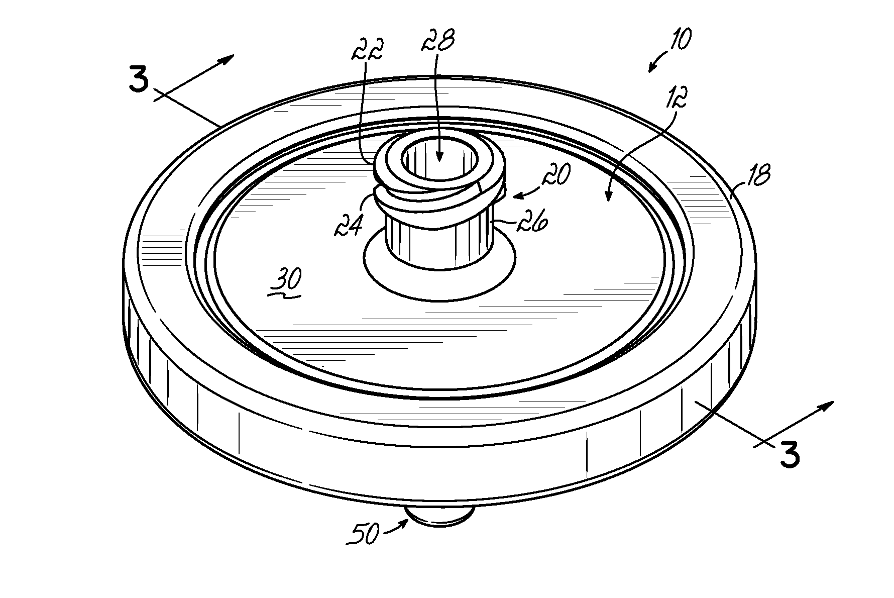
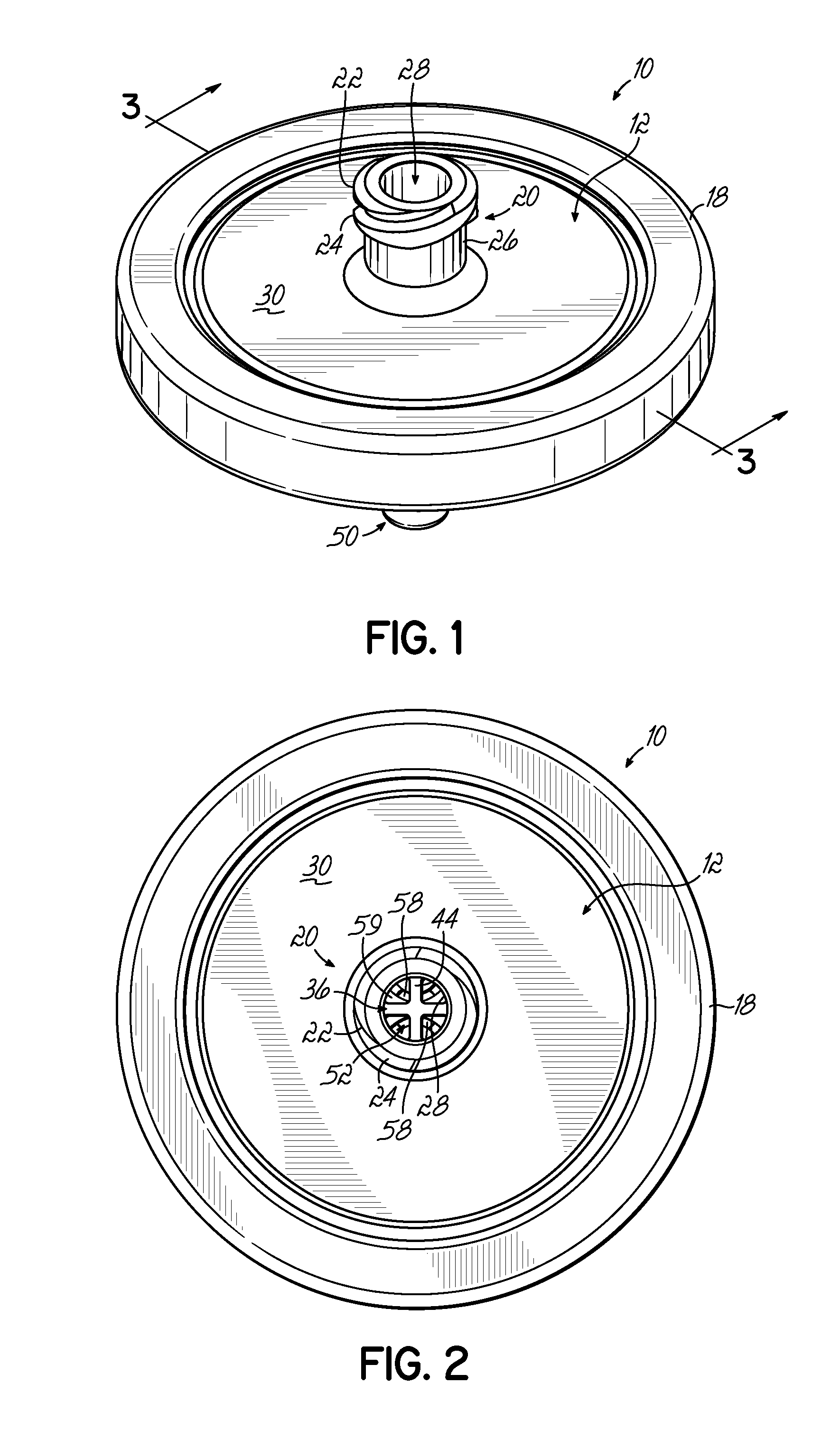
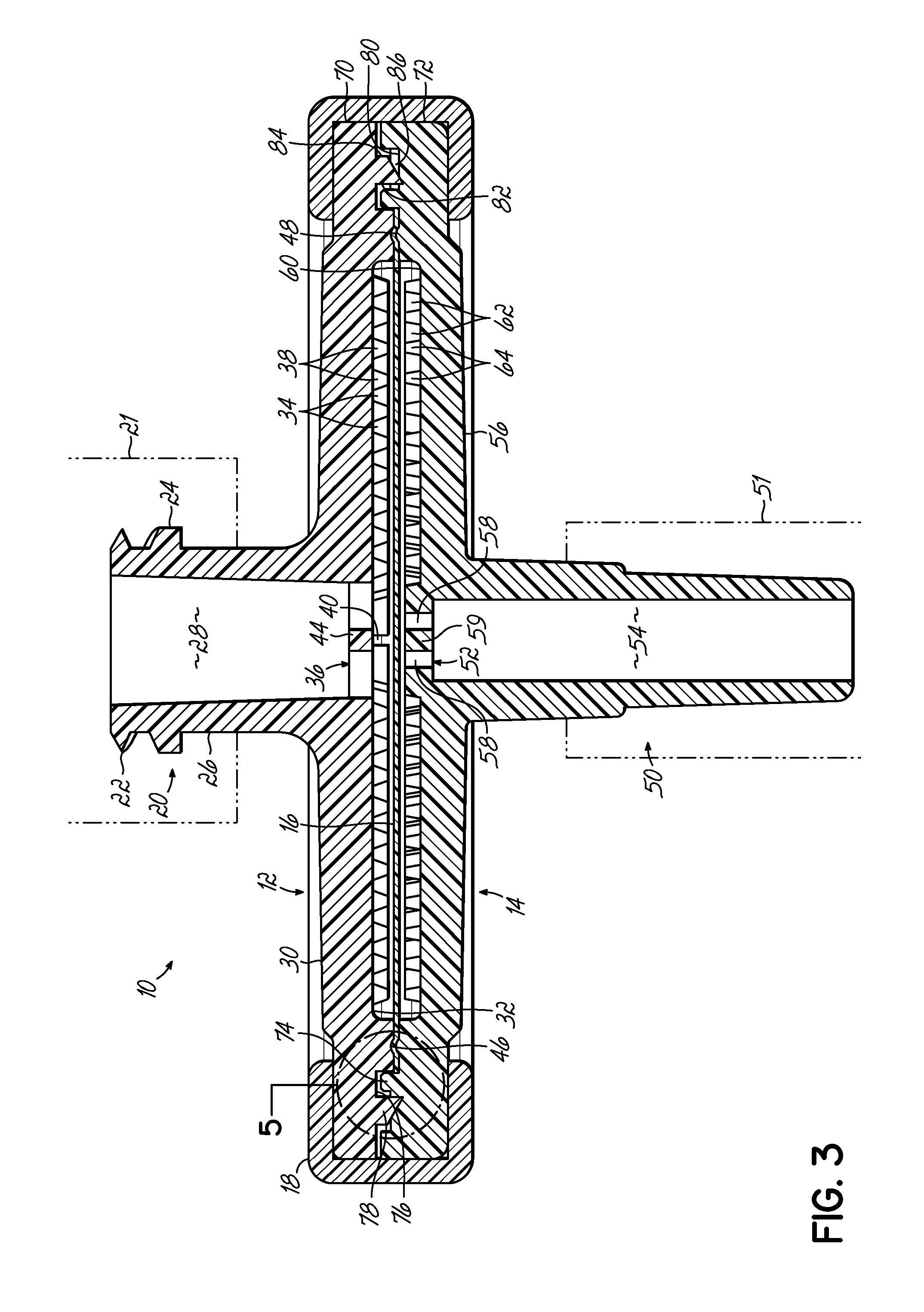
[0029]Turning now to the figures, and in particular to FIGS. 1-3, a syringe filter 10 in accordance with one embodiment of the present invention is shown. While not required, the particular illustrative embodiment is shown as a 30 mm syringe filter (i.e., suitable for use with a 30 mm luer lock).

[0030]The syringe filter 10 includes an inlet portion 12, an outlet portion 14, a membrane 16 located therebetween, and a sealing ring 18 surrounding at least an edge of the inlet portion 12 and the outlet portion 14. The membrane 16 may be selected, at least in part, by the particular application and fluid filtration needs. For example, the membrane 16 may range in construction materials (for example, polytetrafluoroethylene, polysulfone, nylon, polyvinylidene fluoride, cellulose, cellulose acetate, polypropylene, glass microfiber, and so forth) and porosity (with pores ranging from about 0.2 μm to about 5 μm).

[0031]The inlet and outlet portions 12, 14 may be constructed from a moldable, ch...


PUM

PropertyMeasurementUnit
diameteraaaaaaaaaa
diameteraaaaaaaaaa
perimeteraaaaaaaaaa

Abstract

A syringe filter for containing a filter membrane is disclosed and includes first and second fluid distribution surfaces configured to be positioned on opposing sides of a membrane. An inlet port is in fluid communication with the first fluid distribution surface and a first plurality of distribution pathways formed on the first fluid distribution surface. An outlet port is in fluid communication with the second fluid distribution surface and a second plurality of distribution pathways formed on the second fluid distribution surface. The first plurality of distribution pathways is configured to distribute fluid flow from the inlet port to one side of the membrane while the second plurality of distribution pathways is configured to direct fluid flow from another side of the membrane to the outlet port.

Description

FIELD OF THE INVENTION[0001]The present invention relates generally to filtration devices and, more particularly, to syringe filtration devices.BACKGROUND[0002]Syringe filters are single-use filter cartridges that are conventionally used to remove particulates from fluids used in sample preparation protocols, such as during HPLC analysis, ion chromatography, or dissolution testing. In other instances, syringe filters may be coupled to a syringe to remove particulates during a hypodermic injection.[0003]While known conventional syringe filter design has provided a much needed benefit to such uses, there remains some need for improvement. This is particularly true for the manufacture process—high scrap rates, labor-intensive inspection processes, inconsistent product appearance, and periodic contamination of raw materials are just a few of the deficiencies in manufacturing that are experienced.[0004]Furthermore, known conventional product designs include connection ports that are frag...

Claims


Application Information

Patent Timeline
Patent Type & Authority Applications(United States)
IPC IPC(8): B01D29/90B01D35/02
CPCA61M5/165A61M5/36B01D2325/08B01D63/087B01D2313/08A61M2005/1657
Inventor SHICK, LEEMEN LOYKING, BRIAN W.
Owner NAT SCI
Why Eureka
Try Eureka