System for emulating nuclear magnetic resonance well logging tool diffusion editing measurements on a bench-top nuclear magnetic resonance spectrometer for laboratory-scale rock core analyis

a technology of diffusion editing and nuclear magnetic resonance, applied in the field of laboratory and borehole instruments, can solve problems such as uncertainty and ambiguities, and achieve the effects of improving oil recovery, improving oil recovery, and improving the displacement and recovery of reservoir hydrocarbons

Inactive Publication Date: 2013-10-10
SCHLUMBERGER TECH CORP
View PDF4 Cites 11 Cited by
  • Summary
  • Abstract
  • Description
  • Claims
  • Application Information

AI Technical Summary

Benefits of technology

This patent text describes a method for controlling the duration of gradient pulses in magnetic resonance imaging (MRI) to improve the performance of the technique. By adjusting the spacing between initial and subsequent pulses, the method ensures that the gradient pulses do not overlap with the pulses of the magnetic field, which simplifies spin dynamics and reduces off-resonance effects. This allows for longer receive mode acquisition windows and improved signal-to-noise ratio. The method also takes advantage of the fact that observation wells with casing have fewer practical constraints, making it easier to plan the MRI protocols. Overall, this technique enhances the accuracy and efficiency of MRI data acquisition.

Problems solved by technology

The importance of reference measurements arises because most of these interpretation methods (whether for rock properties or for fluid properties) are subject to uncertainties and ambiguities, both in data processing and in the physics of the NMR response, where different rock or fluid properties may give rise to a similar NMR signal or signature.

Method used


Image

  • System for emulating nuclear magnetic resonance well logging tool diffusion editing measurements on a bench-top nuclear magnetic resonance spectrometer for laboratory-scale rock core analyis
  • System for emulating nuclear magnetic resonance well logging tool diffusion editing measurements on a bench-top nuclear magnetic resonance spectrometer for laboratory-scale rock core analyis
  • System for emulating nuclear magnetic resonance well logging tool diffusion editing measurements on a bench-top nuclear magnetic resonance spectrometer for laboratory-scale rock core analyis

Examples


Embodiment Construction

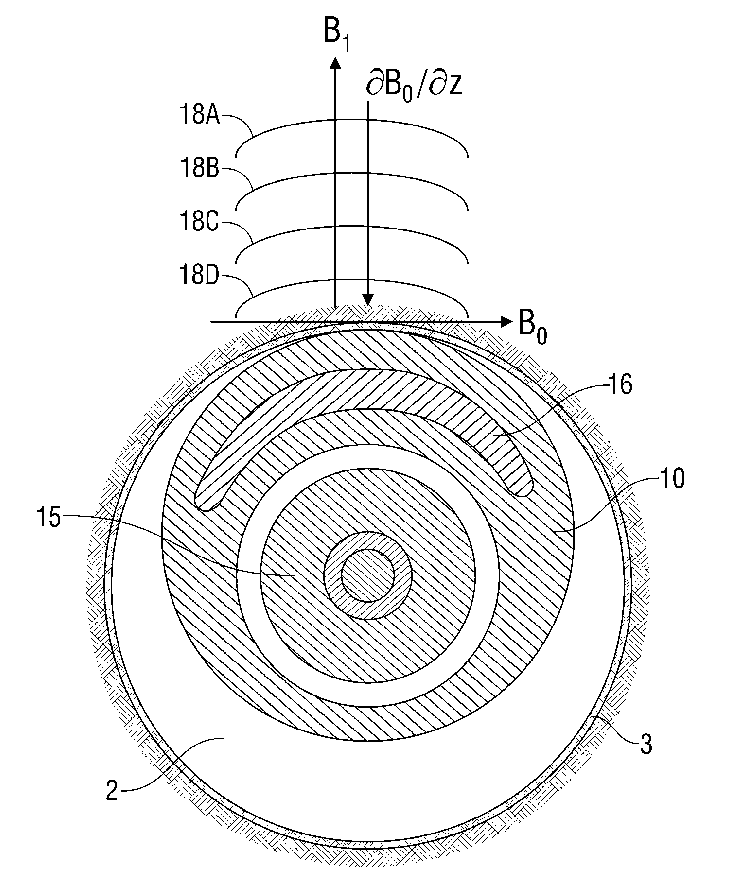
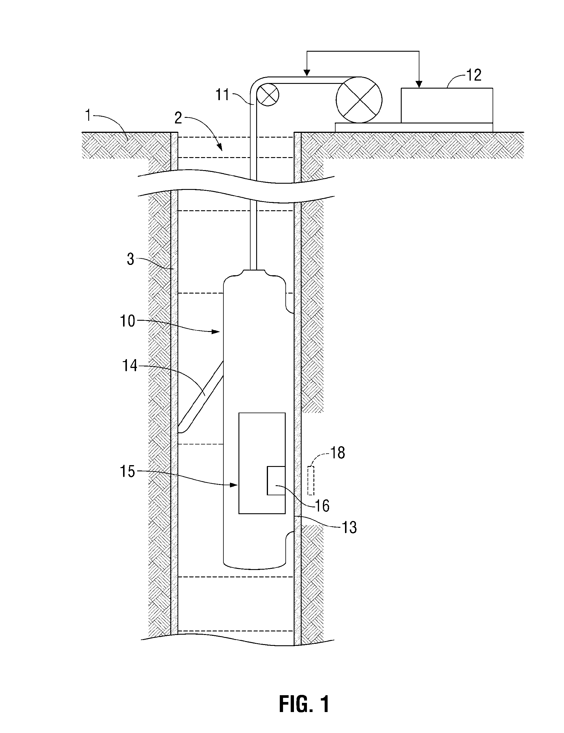
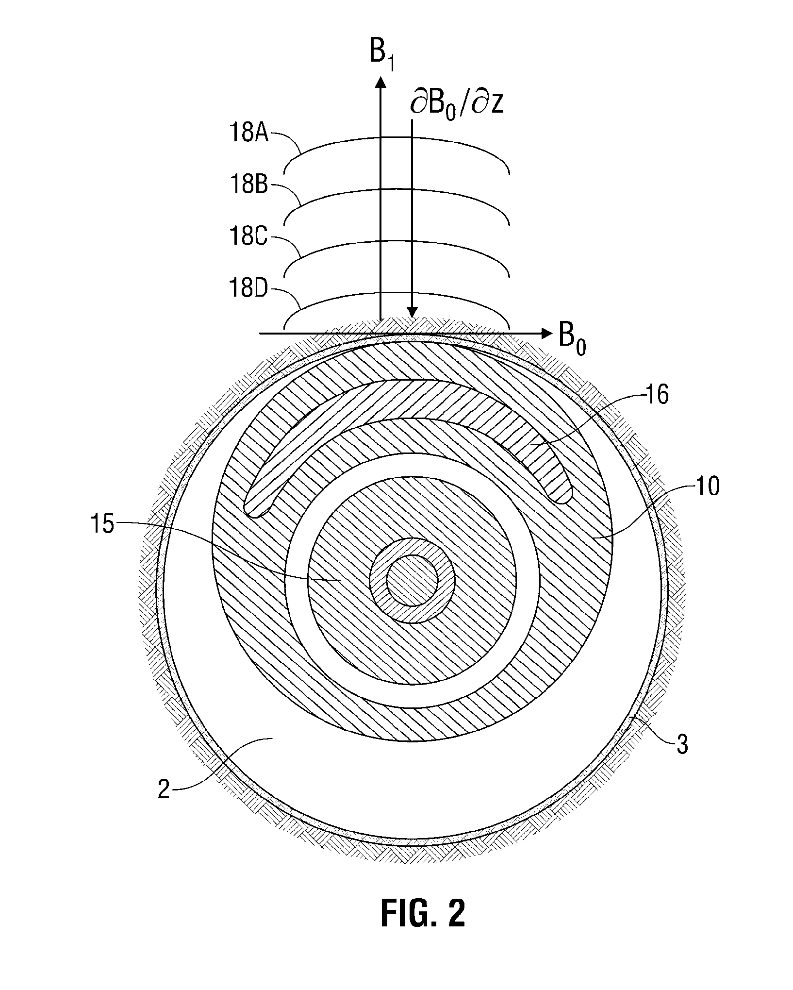
[0043]Embodiments of the invention relate to apparatus and methods for determining reservoir fluid properties using an NMR well logging tool. FIG. 1 shows an exemplary apparatus for investigating a subsurface formation 1 traversed by a borehole 2. The borehole 2 is typically, although not necessarily, filled with a drilling fluid or mud (which contains finely divided solids in suspension) with mudcake 3 on the walls of the borehole. A downhole logging tool 10 is suspended in the borehole 2 on an armored cable 11, the length of which substantially determines the relative depth of the logging tool 10. The cable length is controlled by suitable means at the surface such as a drum and winch mechanism (not shown). Surface equipment, represented at 12, can be of conventional type, and can include a processor subsystem and communicates with the logging tool 10. The logging tool 10 has a face 13 shaped to intimately contact the borehole wall, with minimal gaps or standoff, and a retractable...


PUM


Abstract

A laboratory NMR methodology (and corresponding laboratory apparatus) defines a sample volume. The method stores downhole tool data corresponding to a hydrocarbon-bearing sample collected from a given subsurface formation. The downhole tool data includes parameters pertaining to magnetic fields used by a downhole tool during a suite of NMR measurements of the given subsurface formation. The sample is positioned in the sample volume of the laboratory apparatus, which applies a static magnetic field in the sample volume. Furthermore, the laboratory apparatus applies a suite of NMR measurements to the sample volume to thereby determine a property of the sample. The NMR measurements of the suite each include a pulse sequence of oscillating magnetic field in conjunction with a pulsed-mode gradient field. The pulsed-mode gradient field is based on the stored downhole tool data corresponding to the sample. A laboratory NMR methodology for optimizing downhole NMR measurements is also described.

Description

BACKGROUND OF THE INVENTION[0001]1. Field of the Invention[0002]This invention relates to laboratory and borehole instruments making use of nuclear magnetic resonance (NMR) techniques for evaluating characteristics of hydrocarbon-bearing formations.[0003]2. Description of Related Art[0004]The introduction of pulsed nuclear magnetic resonance (NMR) logging tools in the early 1990s has provided the oil and gas industry with powerful new methods for evaluating petroleum reservoirs. The initial applications of pulsed NMR logging tools were aimed at providing important rock quality properties such as lithology-independent total porosity, free- and bound-fluid porosity, and permeability.[0005]As is well known, the rate of decay of the NMR signal can be described, for example, by a distribution of decay times, which are called transverse relaxation times (T2). It is customary to fit the measured NMR signals to a sum of several decaying single-exponential signals, each with amplitude and as...

Claims


Application Information

Patent Timeline
Patent Type & Authority Applications(United States)
IPC IPC(8): G01R33/48
CPCG01N24/081G01R33/48G01V3/32G01R33/448
Inventor MITCHELL, JONATHANFORDHAM, EDMUND J.
Owner SCHLUMBERGER TECH CORP
Why Eureka
Try Eureka