Apparatus and methods for additive-layer manufacturing of an article

Active Publication Date: 2013-10-17
SIEMENS ENERGY GLOBAL GMBH & CO KG
View PDF6 Cites 192 Cited by
  • Summary
  • Abstract
  • Description
  • Claims
  • Application Information

AI Technical Summary

Benefits of technology

[0023]Advantageously, the applicants have recognised that the provision of tilted scanners in combination with a lens to tilt the focal plane (such that the focal plane is, for example, substantially similar to that which would be provided by a non-tilted scanner) helps to enable the use of a plurality of scanners while minimising any impact on the resultant build quality. Several reasons have been identified for this advantage. Firstly, conventional high build quality additive layer manufacture systems generally require relatively large scanner and lens assemblies in order to provide a small and precise spot size at the focal plane (which may typically require a spot size of about 70 microns). The size of the scanner and/or associated lens assembly m

Problems solved by technology

Firstly, conventional high build quality additive layer manufacture systems generally require relatively large scanner and lens assemblies in order to provide a small and precise spot size at the focal plane (which may typically require a spot size of about 70 microns).
Further, it is desirab

Method used


Image

  • Apparatus and methods for additive-layer manufacturing of an article
  • Apparatus and methods for additive-layer manufacturing of an article
  • Apparatus and methods for additive-layer manufacturing of an article

Examples


Example

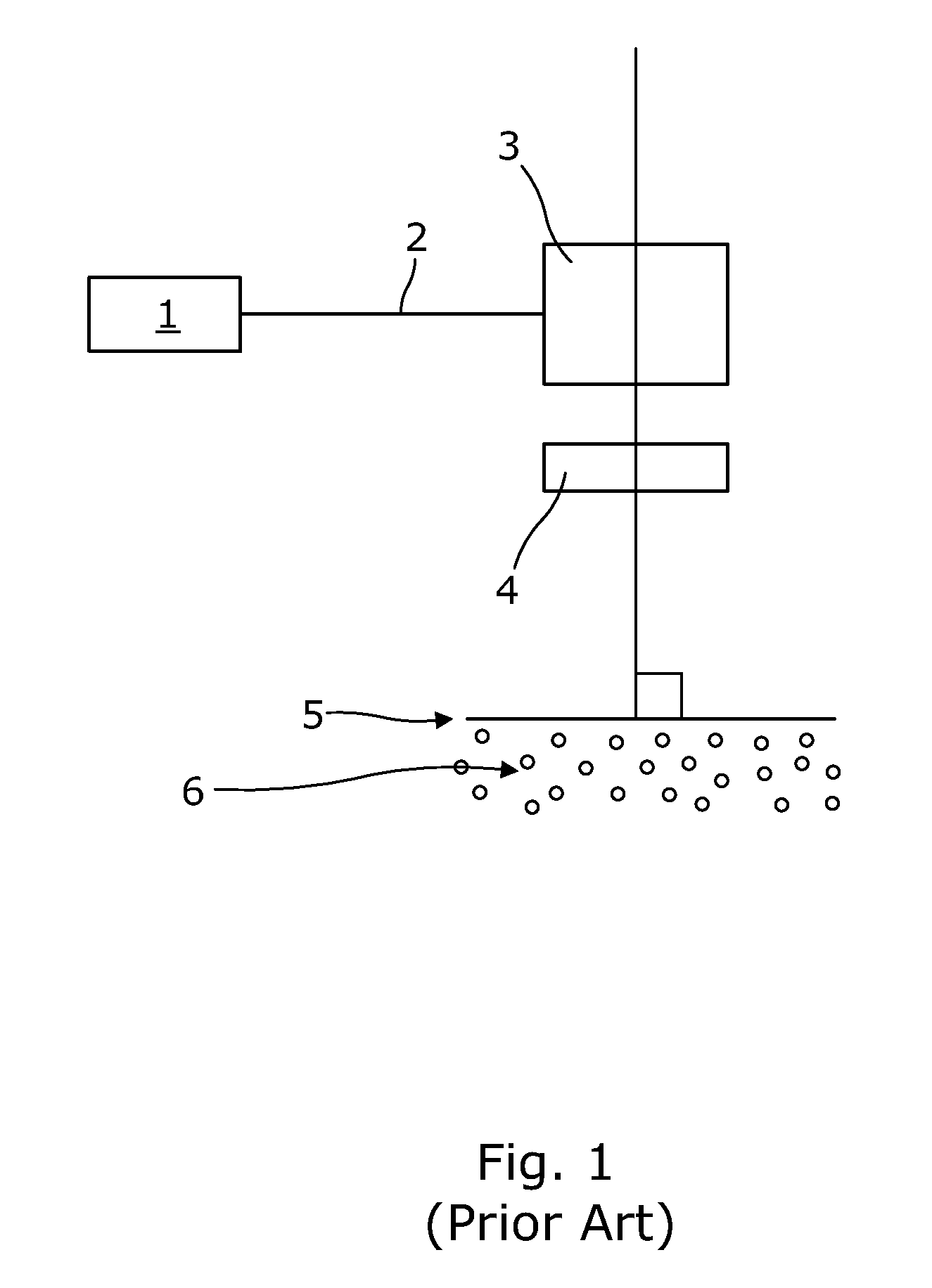
[0039]Turning to FIG. 1, (prior art) the standard known system has a laser 1 that transmits light via a conductor (e.g. optical fibre 2) to a scanner 3, which scans a beam through an F-theta lens 4, which is mounted perpendicular to a focal plane 5 at or near the surface of a powder or fluid bed 6. A typical useful depth of focus of a fixed focus laser with a Gaussian beam profile is approximately + / −2 mm. Typically the useful focal plane is 250×250 mm square and a scanner 3 is located approximately 500 mm from the local plane. The laser spot shape and size is substantially but not exactly constant across the focal plane. As the laser beam moves away from the centre point its shape and size changes becoming oval and expanding in size, thereby reducing power density. This variation determines the size of the useful focal plane—it's an area of process acceptable variation.

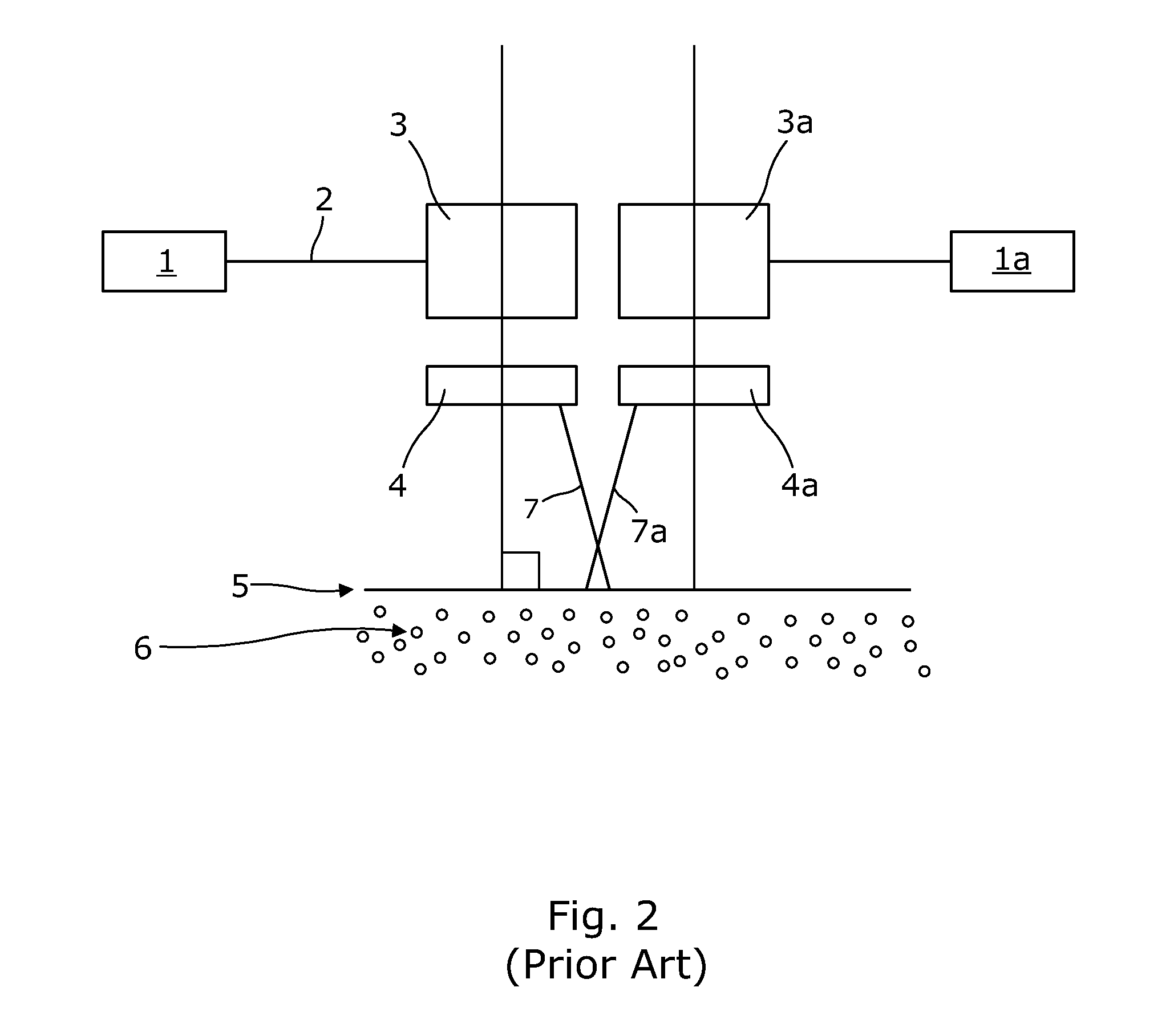
[0040]A development of this is show in FIG. 2 (prior art), where two such arrangements are mounted side by side, w...


PUM

PropertyMeasurementUnit
Poweraaaaaaaaaa
Energyaaaaaaaaaa

Abstract

Apparatus is for additive layer manufacturing of an article from a material which can be rendered solid locally by application of a focused beam of laser radiation at a planar focal plane. The apparatus includes at least two laser beams, respective scanners for each laser beam for scanning the respective laser beams over a planar field, and a support movable stepwise to allow successive manufacturing layer cycles and for supporting material within the field. The entire planar field is common to each scanner and at least one scanner is tilted with respect to the planar field, and the at least one scanner is provided with a lens arranged to generate a focal plane tilted with respect to that scanner.

Description

FIELD OF THE INVENTION[0001]This invention relates to apparatus and methods for additive layer manufacturing using a focused beam of laser energy selectively directed to a planar focal plane adjacent a layer of powder or liquid to carry out a transformation where it strikes—such as a photo polymerisation, sintering or melting of powders thereby building a three dimensional part layer by layer as planar slices.BACKGROUND TO THE INVENTION[0002]The layer of powder or liquid is created by the stepwise sinking of the three dimensional part being built into a liquid vat or powder bed thereby presenting a new layer of untransformed material at the surface and retaining a planar focal plane for the laser at or near that surface. The application of material is distinct from the application of laser energy and the process is characterised in that the laser energy cannot address any layer lower or higher than the current layer in a manufacturing cycle. This is in distinction from methods that ...

Claims


Application Information

Patent Timeline
IPC IPC(8): B29C67/00
CPCB29C67/0077B29C64/153B33Y30/00B29C64/135B33Y10/00B29C64/282B29C64/268B29C64/129Y02P10/25B22F12/44B22F10/36B22F12/49B22F10/28B22F12/45B29C64/20B22F10/00B29C64/277B23K26/082B23K26/342B23K26/046
Inventor GREEN, GORDON R.
Owner SIEMENS ENERGY GLOBAL GMBH & CO KG
Why Eureka
Try Eureka