Rotary electric machine

a rotary electric machine and electric motor technology, applied in the direction of dynamo-electric machines, magnetic circuit rotating parts, magnetic circuit shapes/forms/construction, etc., can solve the problem of large capacitance or a large body, large harmonic distortion of the back electromotive force (b-emf), and the effect of reducing noise vibration

Active Publication Date: 2013-10-17
DENSO CORP
View PDF10 Cites 35 Cited by
  • Summary
  • Abstract
  • Description
  • Claims
  • Application Information

AI Technical Summary

Benefits of technology

[0010]The present disclosure provides a rotary electric machine, which is able to keep harmonic components low and to reduce noise vibration, without the need for an additional circuit element such as a capacitor.
[0014]According to this configuration, it is experimentally ascertained that, when the skew angle is set so as to satisfy θs=kα / 2, harmonic components (particularly, 5-th or more order harmonic components) can be kept low. This allows THD in the formula (1) to be low, and then, noise vibration can be reduced compared to related art. Due to the low THD, circuit elements such as IGBTs (insulated gate bipolar transistors) and FETs (field effect transistors) used in inverters, motor drivers, or the like can be configured by those that have low pressure resistance and are available at relatively low cost. Thus, cost reduction can be achieved.
[0016]In the magnet section, the skew angle θs may be set so as to satisfy θs=kα / 2 where k=S, when the arc ratio θa lies in a range of 2.2S≦θa≦2.4S. In this case, the skew angle θs is set so as to satisfy θs=Sα / 2. According to this configuration, it is experimentally ascertained that, when the skew angle is set so as to satisfy θs=Sα / 2 at 2.2S≦θa≦2.4S, there is relatively small influence from 11-th, 13-th, or the like order harmonic components, and 5-th, 7-th, or the like order harmonic components can be effectively cancelled. Thus, THD can be kept low, and noise vibration can be reduced compared to related art. These effects can be obtained without the need for an additional circuit element such as a capacitor, and then, cost reduction can be achieved.
[0017]In the magnet section, the skew angle θs may be set so as to satisfy θs=kα / 2 where k=1, when the arc ratio θa lies in a range of 2.2≦θa≦3.2. In this case, the skew angle θs is set so as to satisfy θs=a / 2. According to this configuration, it is ascertained that, when the skew angle is set so as to satisfy θs=α / 2 at 2.2≦θa≦3.2, there is relatively small influence from 5-th, 7-th, or the like order harmonic components, and 11-th, 13-th, or the like order harmonic components can be effectively cancelled. Thus, THD can be kept low, and noise vibration can be reduced compared to related art. These effects can be obtained without the need for an additional circuit element such as a capacitor, and then, cost reduction can be achieved.

Problems solved by technology

However, when the permanent magnet rotary electric machine disclosed in JP-B2-3370901 increases the number of slots, its back electromotive force (B-EMF) is likely to have a waveform with large harmonic distortion.
This causes a large capacitance or a large body.
Further, a problem occurs in that, the more intense harmonic components are, the stronger the noise vibration (NZ) is.

Method used


Image

  • Rotary electric machine
  • Rotary electric machine
  • Rotary electric machine

Examples


first exemplary embodiment

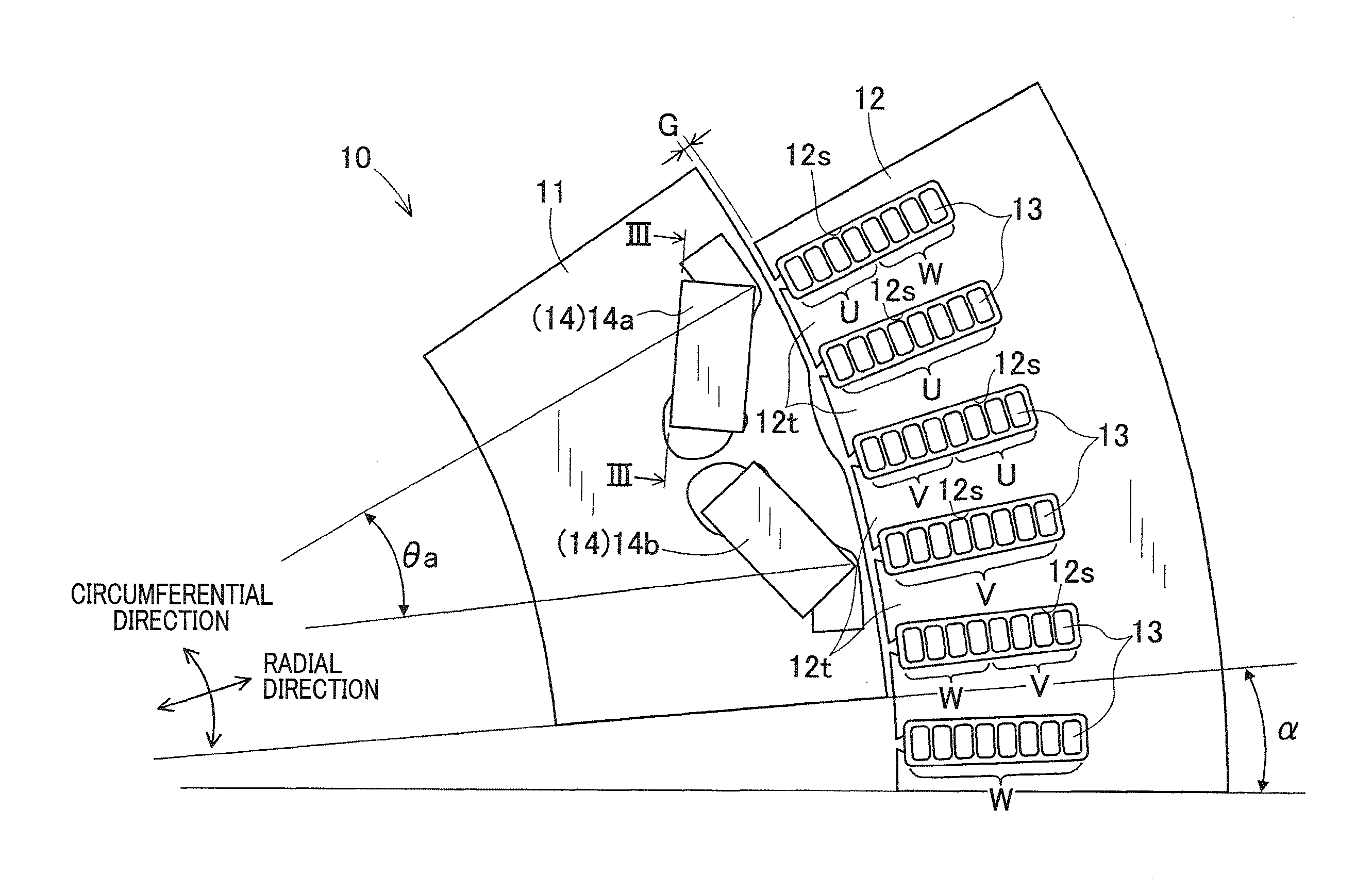
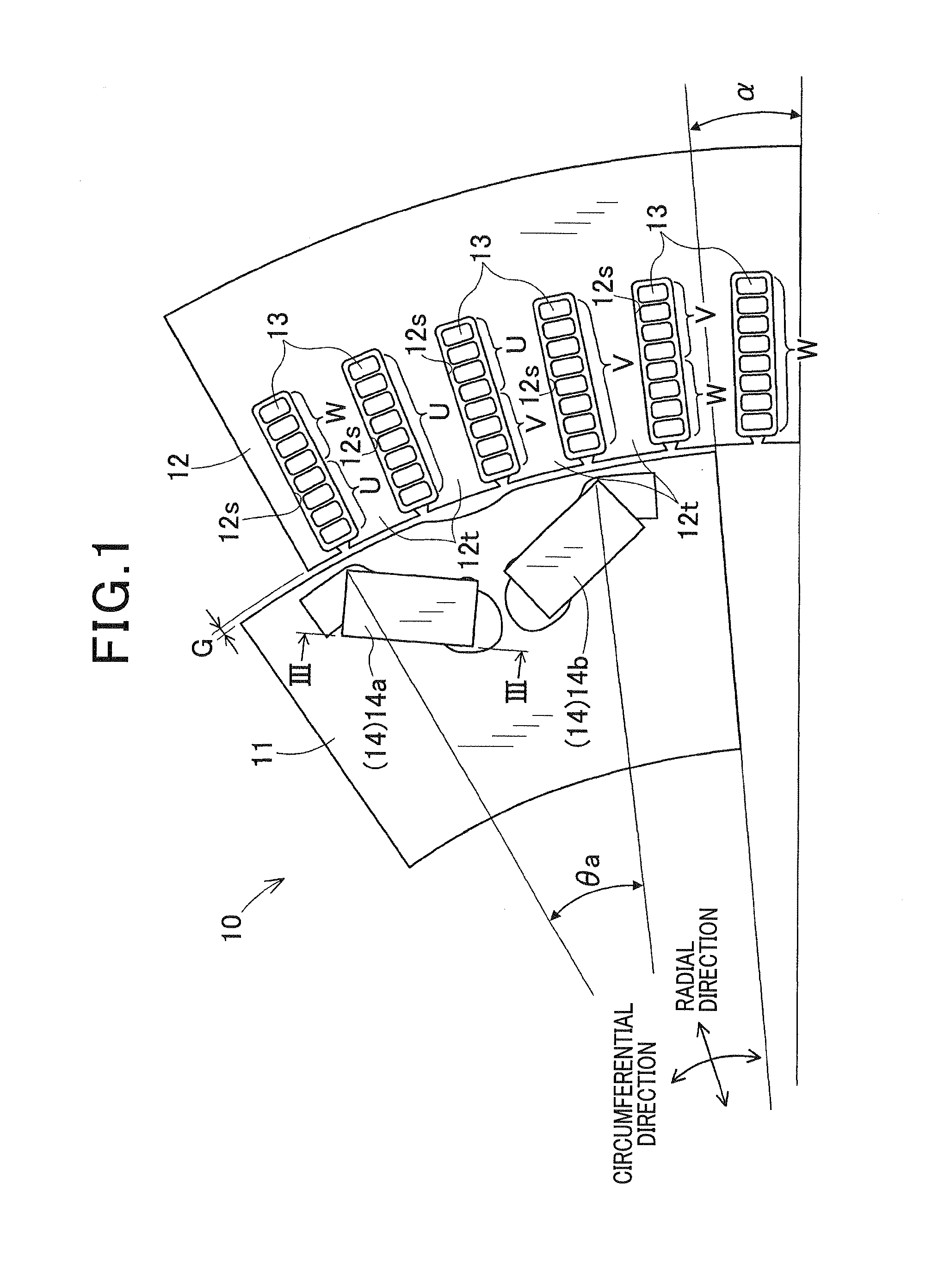
[0046]A first exemplary embodiment is described with reference to FIGS. 1 to 18. FIG. 1 shows a part of an overall configuration of a rotary electric machine 10 having a rotor 11 and a stator 12. FIG. 1 is a cross-section diagram, but the hatching is omitted therefrom to make the description easier to understand. In the rotary electric machine 10, the number of phases, the number of pole pairs (i.e., a pair of north and south poles), and the number of slots can be arbitrarily set. In the present embodiment, the rotary electric machine 10 is configured by an inner rotor type in which a rotor 11 is located at the inner diameter side from the stator 12. In this type, the number of phases is three (i.e., U-phase, V-phase and W-phase), the number of pole pairs is 12, and the number of slots is 72.

[0047]The rotor 11 is located in a rotatable manner relative to the stator 12 via a gap G. This rotor 11 is provided with a plurality of magnet sections 14 (for example, 12 magnet sections in th...

first configuration example

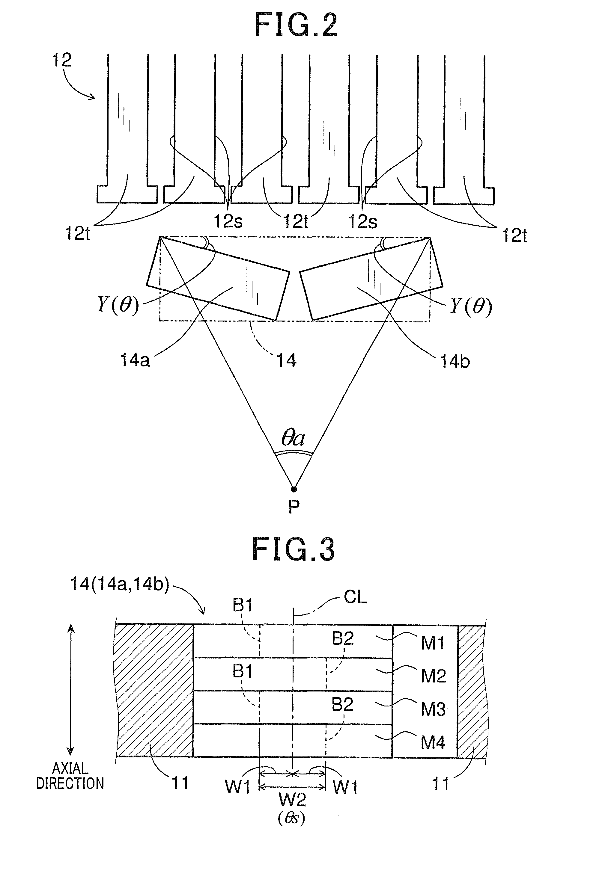
[0076]In a case where the magnet section 14 is configured in such a manner that the arc ratio lies in a range of values from 2.2 to 3.3 (i.e, 2.2≦θa≦3.2), the skew angle is set to α / 2 (i.e., θs=α / 2). This configuration example satisfies the formula (2) at k=1, i.e, the formula (3).

second configuration example

[0077]In a case where the magnet section 14 is configured in such a manner that the arc ratio is a value of 3.3 or lies in a range of values of 3.5 to 4.7 (i.e., θa=3.3 or θa=3.5.to 4.7 including 4.4.to 4.6) which corresponds to θa=1.65S or θa=1.75Sθa≦2.35S if the slot factor is 2 (i.e., S=2), the skew angle is set to Sα / 2 (i.e., θs=Sα / 2). In this embodiment, the slot factor is set to a value of 2 (i.e., S=2), and then, a range of θa=4.4.to 4.6 corresponds to a range of θa=2.2S to 2.3S. Here, if the slot factor is set to a value 3 (i.e., S=3), then a range of θa=4.4.to 4.6 corresponds to a range of θa=1.46S to 1.53S. This configuration example satisfies the formula (2) at k=S, i.e, the formula (4).

[0078]According to the above-described first exemplary embodiment, the following effects can be obtained.

[0079](a) The rotary electric machine 10 is configured by setting the skew angle so as to satisfy:

θs=kα / 2

[0080]where: (i) S is a slot factor which is a ratio of the slots 12s relative t...


PUM


Abstract

A rotary electric machine includes a stator and a rotor located in a rotatable manner relative to the stator via a gap. The stator includes a multi-phase stator winding that is held in a plurality of slots formed in the stator. The rotor includes at least one magnet section embedded therein so as to face the slots. The magnet section includes a plurality of axially laminated magnets with a skew angle which is an angle of a positional difference between the magnets. This skew angle θs is set so as to satisfy θs=kα / 2 where α is a slot pitch which is an angle between the slots, and k is a coefficient set based on: an arc ratio θa being an angle covering an area in which magnetic flux radially flows from the magnetic section; and a slot factor S being a ratio of the slots relative to the magnet section.

Description

CROSS-REFERENCE TO RELATED APPLICATION[0001]This application is based on and claims the benefit of priority from earlier Japanese Patent Application No. 2012-091241 filed Apr. 12, 2012, the description of which is incorporated herein by reference.BACKGROUND[0002]1. Technical Field[0003]The present invention relates to a rotary electric machine having a stator and a rotor.[0004]2. Related Art[0005]In related art, there is disclosed a technique for a permanent magnet rotary electric machine, in order to reduce a peak value of an induced voltage generated when a vehicle is braked or traveling downhill (see, for example, JP-B2-3370901). This permanent magnet rotary electric machine has a stator and a rotor with a plurality of permanent magnets. In the stator, a plurality of slots are formed. In these slots, three-phase stator windings, i.e., U-phase, V-phase and W phase windings are held. This rotary electric machine is configured so as to satisfy θ≈(n+0.5)×τs where n is a natural numbe...

Claims


Application Information

Patent Timeline
Patent Type & Authority Applications(United States)
IPC IPC(8): H02K1/27
CPCH02K1/274H02K21/14H02K29/03H02K1/276H02K1/2766H02K2201/06H02K2213/03
Inventor TAKAHASHI, YUKISEGUCHI, MASAHIRO
Owner DENSO CORP
Why Eureka
Try Eureka