Device and system for load driving

Active Publication Date: 2013-10-17
INVENTRONICS HANGZHOU
View PDF3 Cites 5 Cited by
  • Summary
  • Abstract
  • Description
  • Claims
  • Application Information

AI Technical Summary

Benefits of technology

The invention aims to improve the reliability and reduce complexity of a load driving device and system. The electric energy supplying unit includes at least two output voltage adjustable units, which are connected in parallel to achieve system expansion and redundant backup of electric energy supplying. The input of a sampling unit connects to the output of the electric energy supplying unit and samples the total current output from the unit, reducing the reliability risk of the driving device and the load unit. The driving device and load unit can be separated, increasing the set distance between them and reducing heat source. The output voltage adjustable unit reduces the loss of the current-limiting circuit of the load unit, further improving the reliability of the load driving system. The electric energy transmission between the electric energy supplying unit and the load unit can be achieved by two connection wires, simplifying the circuit design and reducing complexity. The output voltage of the electric energy supplying unit can automatically adjust with the variation of the load branches, eliminating the need for separate open protection circuits and reducing complexity and cost.

Problems solved by technology

Firstly, in order to facilitate the minimum value sampling circuit of the driver to perform a voltage sampling from the post-stage circuit, the linear adjustment current-limiting circuit 203 of each LED branch often needs to be enclosed inside the driver, the loss of the adjustment transistor is large when the voltage difference between the multiple of LED branches is large, resulting in serious heat of the driver. Moreover, the driver is generally placed nearby the LED light source inside the LED lighting device, thus the temperature thereof will be higher, which affects the reliability of the driver seriously.
Secondly, the output voltage control circuit 204 of the output voltage adjustable voltage source 201 in the front-stage needs to sample the voltage of the post-stage circuit composed of a LED and the corresponding linear adjustment current-limiting circuit 203, so that the wiring between the front-stage output voltage adjustable voltage source 201 and the post-stage circuit is complicated. Moreover, when an open circuit fault occurs in a certain LED load, the drain voltage of the linear adjustment transistor is zero. Therefore, it is necessary to further provide an open circuit protection for each LED load, so as to ensure that other LED loads in which no fault occurs can operate normally in this case, which further increases the complexity of the circuit.

Method used


Image

  • Device and system for load driving
  • Device and system for load driving
  • Device and system for load driving

Examples


Embodiment Construction

[0056]Specific implementations of a load driving system according to an embodiment of the invention will be described in detail in conjunction with the drawings hereinafter.

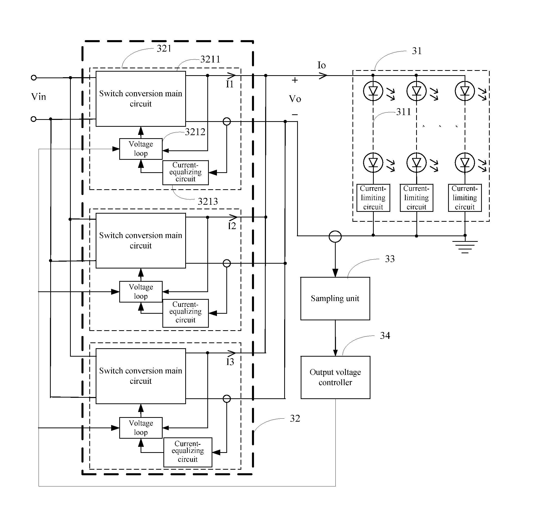
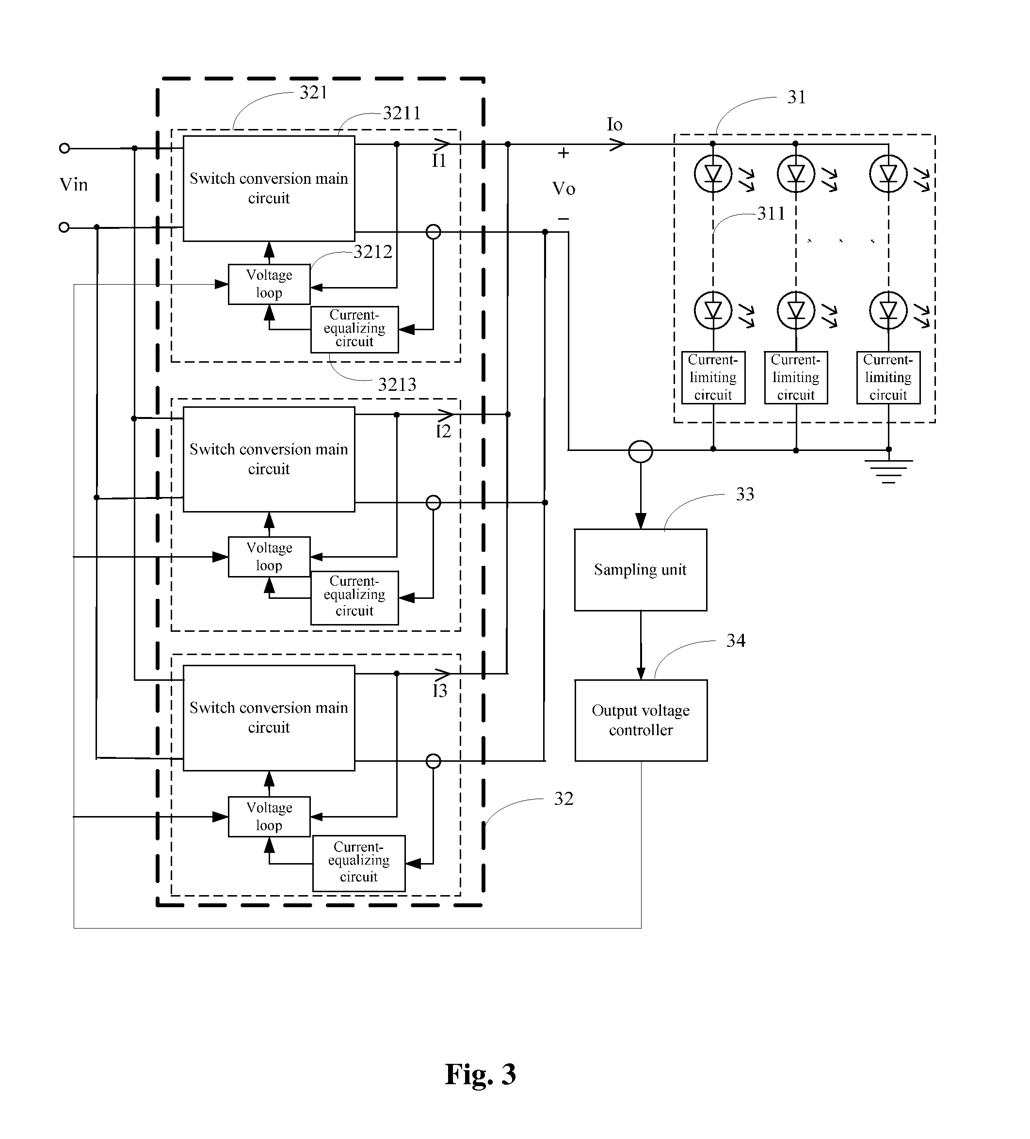
[0057]A load driving system according to an embodiment of the invention includes:

[0058]a load unit including at least one load branch, in which a first end of each load branch is connected to a first end of the load unit and a second end of each load branch is connected to a second end of the load unit;

[0059]an electric energy supplying unit including at least two output voltage adjustable units, in which a first output of each output voltage adjustable unit is connected to a first output of the electric energy supplying unit and a second output of each output voltage adjustable unit is connected to a second output of the electric energy supplying unit, the first output of the electric energy supplying unit is connected to the first end of the load unit and the second output of the electric energy supplying unit ...


PUM


Abstract

A device and system for load driving. The device includes: an electric energy supplying unit including at least two units with output voltage adjustable; a sampling unit, with the input thereof connected to either end of a load unit for sampling the current of that end and sending the sampled current to an output voltage controller; the output voltage controller, with the input thereof connected to the output of the sampling unit for outputting voltage control signal to each unit with output voltage adjustable, according to the sampled current, so as to control the difference between the output voltage of each unit with output voltage adjustable and the maximum load voltage in a load branch to be not greater than a preset difference threshold, with the difference threshold being greater than or equal to zero. The device and system for load driving can improve the reliability of the driving device and can reduce the complexity of the circuit.

Description

[0001]This application claims the priority of Chinese Patent Application No. 201010607074.3, entitled “LOAD DRIVING DEVICE AND LOAD DRIVING SYSTEM”, filed with the Chinese Patent Office on Dec. 27, 2010, which is incorporated by reference in its entirety herein.FIELD OF THE INVENTION[0002]The invention relates to the field of circuit, and particularly to a load driving device and a load driving system.BACKGROUND OF THE INVENTION[0003]Most of the existing Light Emitting Diode (LED) luminaries have the structures which is designed based on the conventional gas discharge lamp and Tungsten lamp. The driving scheme which follows the conventional idea includes: providing one driver for one light source, and using a conventional AC / DC conversion technique with single-path or multi-path output. As shown in FIG. 1, a lighting device includes a light source and a driver, and is controlled by a distribution switch. As shown in FIG. 1, the driver is provided nearby the light source inside the l...

Claims


Application Information

Patent Timeline
IPC IPC(8): H05B33/08H05B44/00
CPCH05B33/0815H05B45/46H05B45/3725
Inventor HUA, GUICHAOGE, LIANG'ANYU, HANGDONG
Owner INVENTRONICS HANGZHOU
Why Eureka
Try Eureka