High-voltage battery charging simulation system and operating method thereof

a simulation system and battery technology, applied in the field of battery charging simulation system, can solve the problems of only being able to perform the detection process for charging stations and communication devices, unpredictable errors may appear, and damage to the pack, so as to prevent errors or instability, detect and maintain efficiency in the real charging process, and raise the safety of detection

Active Publication Date: 2013-10-17
SHIP & OCEAN INDUSTRIES R&D CENTER
View PDF3 Cites 13 Cited by
  • Summary
  • Abstract
  • Description
  • Claims
  • Application Information

AI Technical Summary

Benefits of technology

[0008]The high-voltage battery charging simulation system and the operating method of the present invention are capable of simulating characteristic changes and operate process of the real battery back when it is in the charging state. By adopting the high-voltage battery charging simulation system on the detecting of the peripheral equipment like charging stations and the communication devices, the efficiency in the real charging process can be detected and maintained. This could avoid the real battery pack connecting to the peripheral equipment and prevent the error or instability from the internal parts of peripheral equipment resulting in overheat, damage or explosion. The safety of detecting can be raised and the loss of the cost can be diminished. In addition, the simulation battery management system can be an industrial or embedded apparatus with controlling and displaying functions. The charging conditions of the battery pack can be simulated by simple configuration so as to make the system more convenient.

Problems solved by technology

It is well known that detecting processes can only be performed respectively for charging stations and communication devices.
Thus, unpredictable errors may come out when the detecting processes are performed for the charging stations and multi-party communication devices in operation mode.
If the charging stations or the communication devices are in an unstable state, the battery pack may be damaged due to overheated or the battery pack may even cause explosion.
The aforementioned method not only wasted the time to input the characteristics, but also could not simulate changes of the battery pack when the battery pack was in a charging state.
The aforementioned method was not capable of simulating the changes of the battery pack when the battery pack was in the charging state.

Method used


Image

  • High-voltage battery charging simulation system and operating method thereof
  • High-voltage battery charging simulation system and operating method thereof
  • High-voltage battery charging simulation system and operating method thereof

Examples


Embodiment Construction

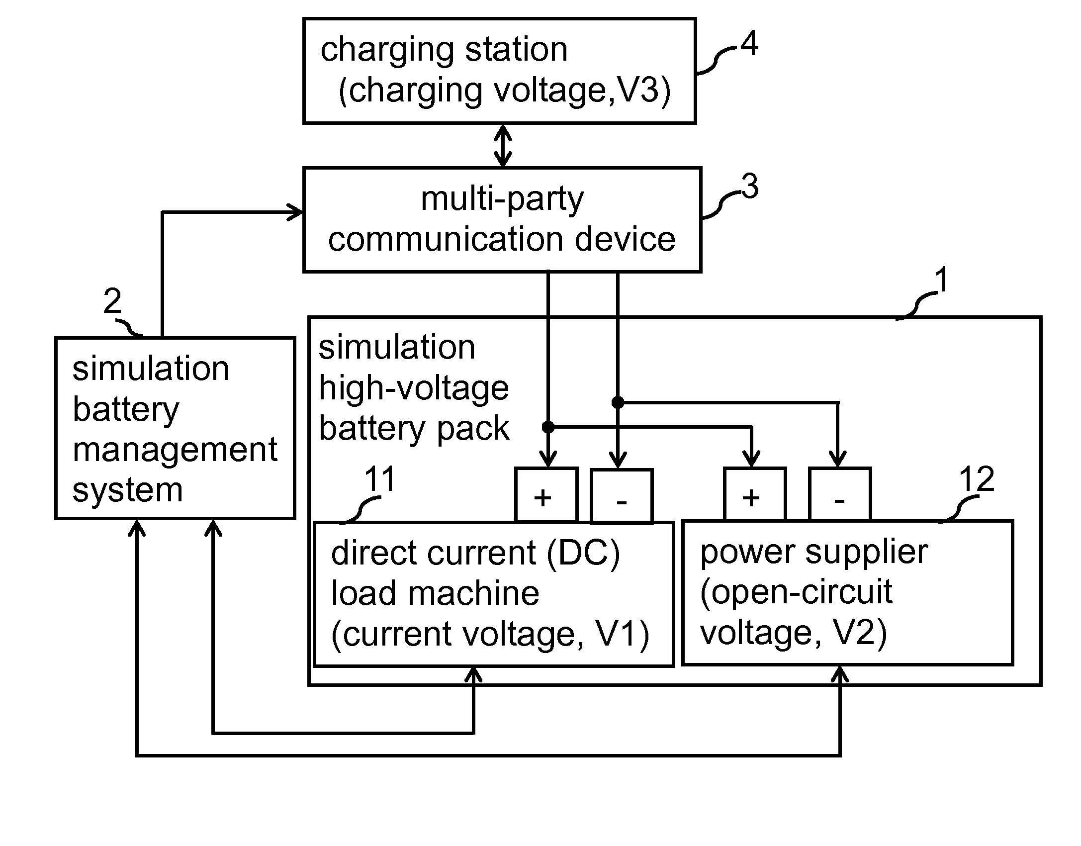
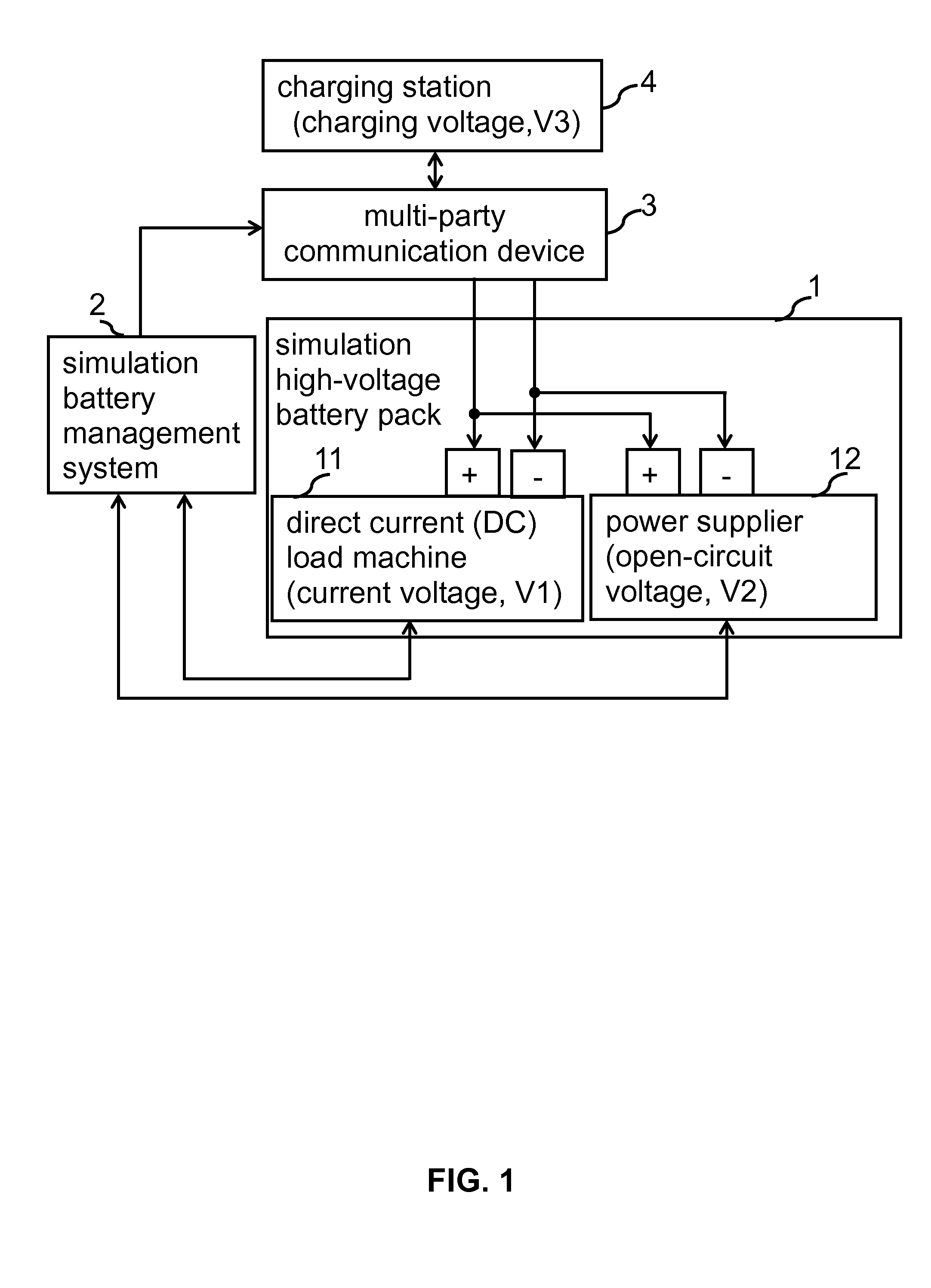
[0011]FIG. 1 is a block diagram of an embodiment of a high-voltage battery charging simulation system. The high-voltage battery charging simulation system comprises a simulation high-voltage battery pack 1, a simulation battery management system 2, a multi-party communication device 3, and a charging station 4. The simulation high-voltage battery pack 1 includes a direct current (DC) load machine 11 to simulate a current voltage (V1) of the simulation high-voltage battery pack 1 and a power supplier 12. In addition, the DC load machine 11 consumes a charging voltage (V3) outputted by the charging station 4 so as to simulate the power consumption of a real battery pack when the real battery pack is charged by the charging station 4.

[0012]The anode and the cathode of the power supplier 12 respectively connects to the anode and the cathode of the DC load machine 11 so as to simulate an open-circuit voltage (V2) of the simulation high-voltage battery pack 1. As such, the open-circuit vo...


PUM


Abstract

The present invention relates to a high-voltage battery charging simulation system that includes a simulation high-voltage battery pack, a simulation battery management system, a multi-party communication device, and a charging station. The voltage of the simulation high-voltage battery pack can be calculated and updated immediately by the simulation battery management system to simulate the feature of real battery pack, so that it can detect the operation of the multi-party communication device and the charging station.

Description

BACKGROUND OF THE INVENTION[0001]1. Field of the Invention[0002]The invention relates in general to a battery charging simulation system, and more particularly to a high-voltage battery charging simulation system and an operating method thereof.[0003]2. Description of the Related Art[0004]It is well known that detecting processes can only be performed respectively for charging stations and communication devices. Thus, unpredictable errors may come out when the detecting processes are performed for the charging stations and multi-party communication devices in operation mode. During the detecting process, the charging stations and the communication devices have to be connected to battery packs. If the charging stations or the communication devices are in an unstable state, the battery pack may be damaged due to overheated or the battery pack may even cause explosion. Therefore, it is very important to use simulation devices to perform the detecting process.[0005]In the disclosure of ...

Claims


Application Information

Patent Timeline
Patent Type & Authority Applications(United States)
IPC IPC(8): H02J7/00
CPCG01R31/36G01R31/367
Inventor CHOU, SHEAN-KWANGLIN, HUNG-HSILIN, CHIH-HUNGCHEN, SHENG-HUA
Owner SHIP & OCEAN INDUSTRIES R&D CENTER
Why Eureka
Try Eureka