Method For Automatic Quantification Of Dendrite Arm Spacing In Dendritic Microstructures

a dendrite arm spacing and automatic quantification technology, applied in the field of metal casting microstructure quantitative, can solve the problems of time-consuming and heavily dependent on skills

Active Publication Date: 2013-10-17
GM GLOBAL TECH OPERATIONS LLC
View PDF14 Cites 4 Cited by
  • Summary
  • Abstract
  • Description
  • Claims
  • Application Information

AI Technical Summary

Benefits of technology

[0012]According to another aspect of the present invention, an article of manufacture is disclosed. The article includes a computer usable medium with computer readable program code embodied therein for quantifying DAS properties of a cast material such that it can be used in a general-purpose computer or specifically-adapted computer such as discussed above. Specifically, such computer readable program code includes a portion for causing the computer to accept or read data that corresponds to digital information taken of a sample of the cast material, as well as a portion for causing the computer to process the information into DCS information, in addition to a portion for converting the DCS to DAS based on either a theoretical relationship between these two forms of information or an empirical relationship. In addition, the program that is embodied on the computer-readable medium includes a portion for outputting the DAS information. Such output may be in machine-readable or human-readable fo...

Problems solved by technology

The problem with the measure of DAS is that it has to be measured manually by identifying the well defined dendrite arms in the image ...

Method used


Image

  • Method For Automatic Quantification Of Dendrite Arm Spacing In Dendritic Microstructures
  • Method For Automatic Quantification Of Dendrite Arm Spacing In Dendritic Microstructures
  • Method For Automatic Quantification Of Dendrite Arm Spacing In Dendritic Microstructures

Examples


Embodiment Construction

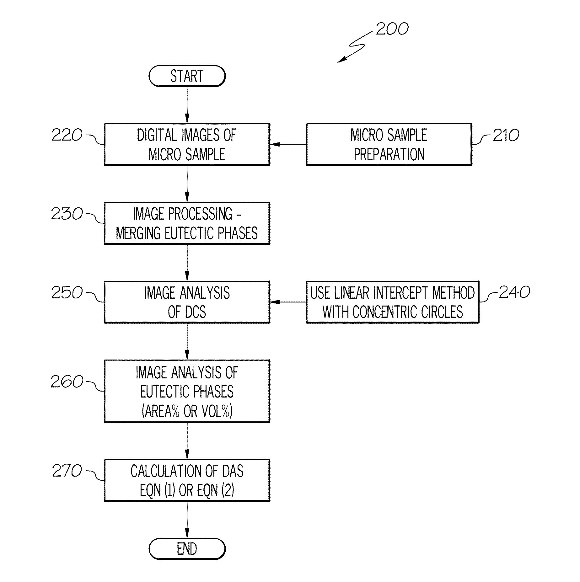
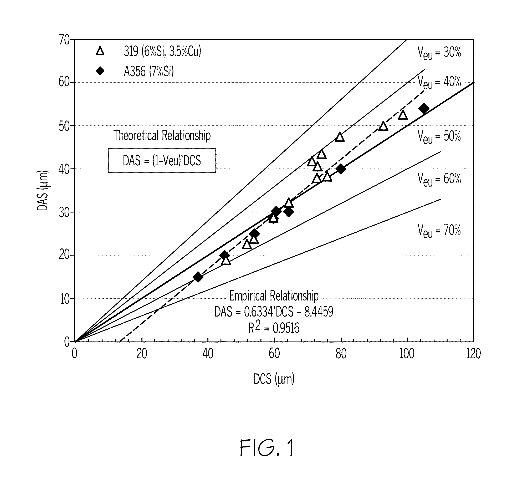
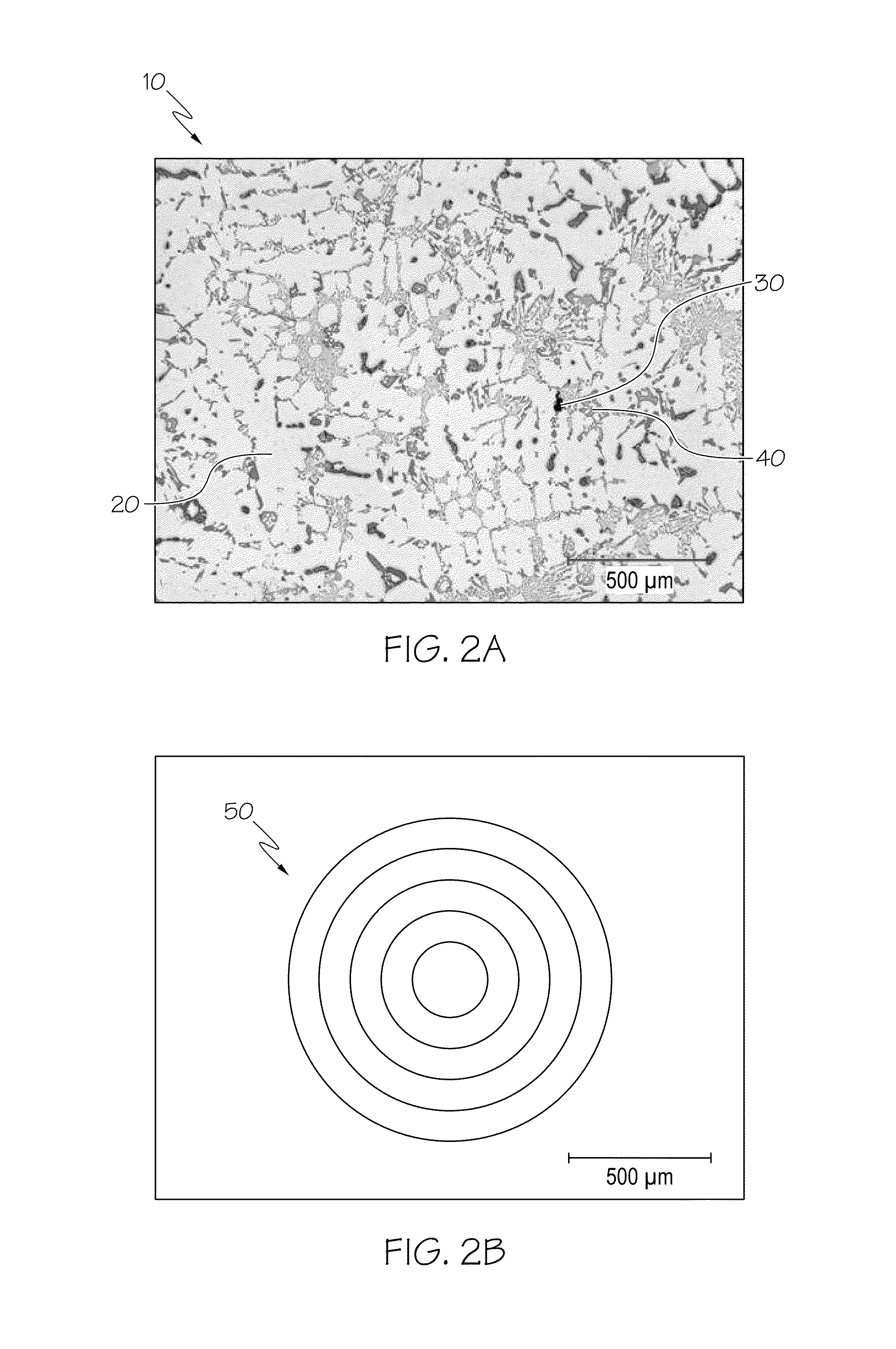
[0023]Referring first to FIGS. 1 and 7, as mentioned above, one of two approaches is used to convert a measured or sampled DCS value to DAS. As discussed above, an automated way to predict DAS distribution within a cast component may include taking a micro sample for the casting location of interest and analyzing it through a computer-based image analyzer. Referring with particularity to FIG. 7, an image analyzer system (also referred to herein as image analysis system, image analyzer or the like) 300 includes a computer 310 or related data processing equipment that includes a processing unit 310A (which may be in the form of one or more microprocessors), one or more mechanisms for information input 310B (including a keyboard, mouse or other device, such as a voice-recognition receiver (not shown)), as well as a one or more loaders 310C (which may be in the form of magnetic or optical memory or related storage in the form of CDs, DVDs, USB port or the like), one or more display scre...


PUM


Abstract

A method to automatically quantify dendrite arm spacing in dendritic microstructures. Once a location of interest in a cast material specimen has been identified, the information contained in it is automatically analyzed to quantify dendrite cell size information that is subsequently converted into a quantified dendrite arm spacing through an empirical relationship or a theoretical relationship. In one form, the relationship between DCS and DAS is such that the DAS in dendritic structure of cast aluminum alloys may be automatically determined from the measurement of one or more of dendrite cell size and the actual volume fraction of the eutectic phases in the local casting microstructure. Non-equilibrium conditions may be accounted for in situations where a theoretical volume fraction of a eutectic phase of the alloy in equilibrium condition is appropriately modified. Thus, in situations where equilibrium conditions—such as those where the casting is cooled very slowly during solidification—does not apply (such as during rapid cooling and consequent solidification), the eutectic measured in the non-equilibrium condition, which can be smaller than the theoretical value in equilibrium, can be accounted for.

Description

[0001]This application claims priority to U.S. Provisional Application 61 / 623,145, filed Apr. 12, 2012.BACKGROUND OF THE INVENTION[0002]The present invention relates generally to the quantification of microstructural fineness of metal castings, and more particularly to the automated quantification of dendrite arm spacing (DAS) in dendritic microstructures of metal castings as a way to avoid having to take such measurements manually.[0003]The resulting microstructure of all cast aluminum-based components (such as engine blocks, cylinder heads, transmission parts or the like) is naturally determined generally by the alloy composition and more particularly by the solidification conditions. In hypoeutectic alloys (i.e., those that contain more aluminum than corresponds to the eutectic with the other alloy constituents in order to reduce the secondary dendrite arm spacing upon solidification, examples of which include A356 and 319, both A1-7% Si—Mg variants), the materials tend to solidi...

Claims


Application Information

Patent Timeline
IPC IPC(8): G06T7/00
CPCG06T7/0004G06T2207/10056G06T2207/30116G06T7/41G06F18/00
Inventor WANG, QIGUIKNIGHT, JAMES W.
Owner GM GLOBAL TECH OPERATIONS LLC
Why Eureka
Try Eureka