
Fabric-Faced Floor Coverings with Micro-Spring Face Structures

a technology of face structure and fabric, applied in the field of fabric face laminates, can solve the problems of composites tending to deform out of plane, lack of textile look, softness or sound dampening qualities of textile products, general lack of superior stability of solids, etc., and achieves the effect of low face layer stretch for facial stability, high gathering ability to lay flat, and small scal

Active Publication Date: 2013-10-17
J&J FLOORING GRP LLC
View PDF6 Cites 16 Cited by
  • Summary
  • Abstract
  • Description
  • Claims
  • Application Information

AI Technical Summary

Benefits of technology

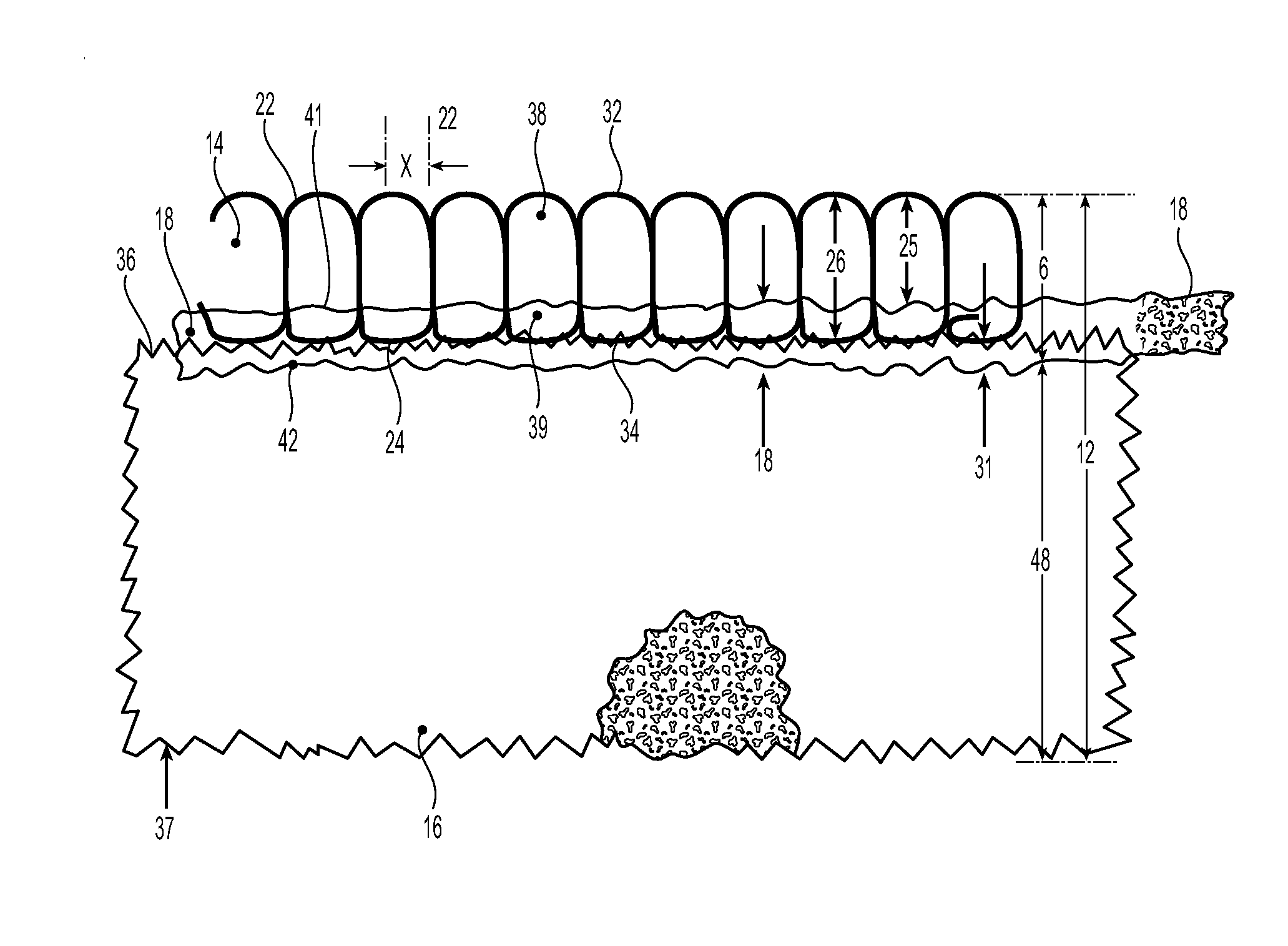
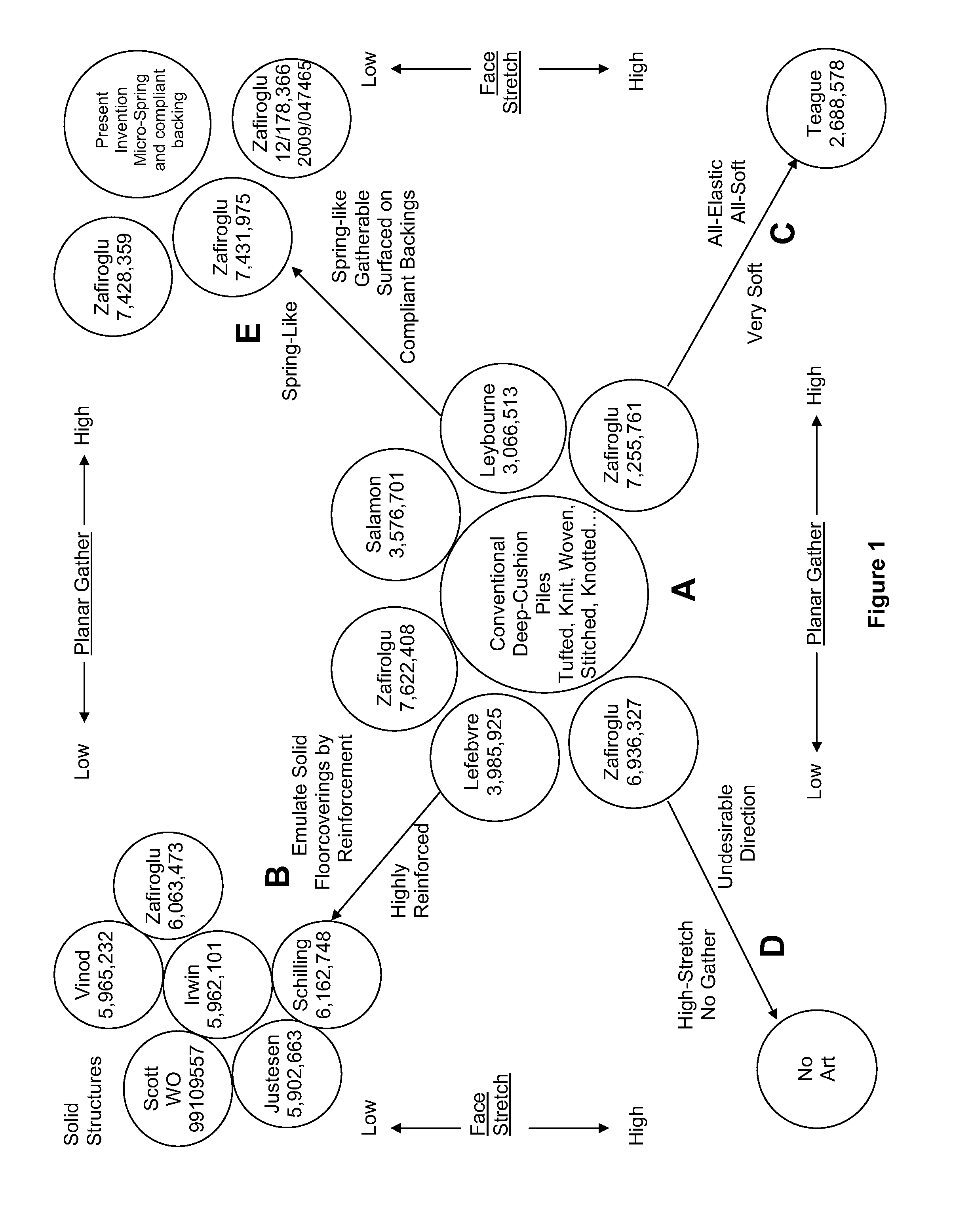
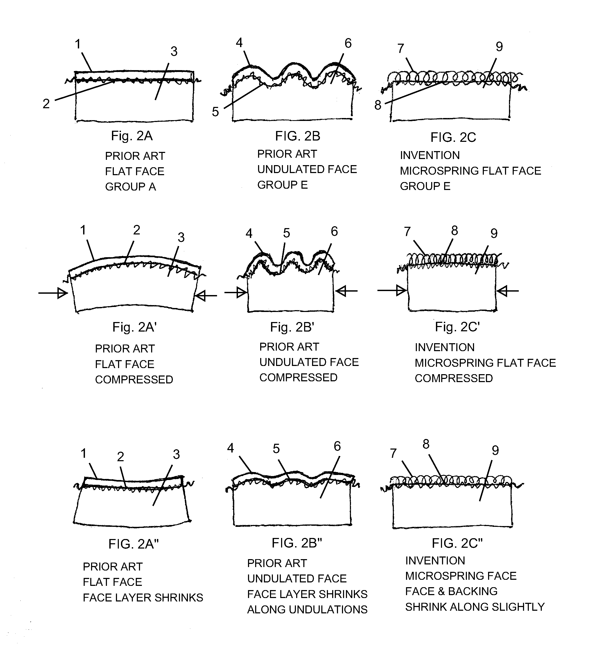
The present invention is a floor covering that occupies the most optimal area of FIG. 1, which is high gathering ability to lay flat and low face layer stretch for facial stability. The face layer of the present invention is made up of yarns that form spring-like coils or loops, which are smaller in scale than the undulated face layers of the other references. The inventive yarns are able to planarly compress or gather as they are held by porous and conformable adhesive, without the substantial resistance of secondary reinforcing base layers. This results in a floor covering that is more comfortable, stable, and durable.

Problems solved by technology

However, these products lack the textile look, softness or sound dampening qualities of textile products.
They generally lack the superior stability of the solid floorcoverings because they are, in general, built with layers of organic or polymeric materials and, as the layers expand or contract at different rates with temperature or humidity, the composites tend to deform out of plane.
Such a floorcovering is undesirable in high-wear commercial, institutional or other such applications, because traffic is impeded by the stretchy surface and repeated stretch can cause delamination with heavy use.
Group C floorcoverings may be too elastic to resist foot traffic.
Such floorcoverings are undesirable, because they would be too elastic / stretchy to walk on and would also buckle out-of-plane due to low gathering.
No products of this nature have been developed in prior art.
They provide softness, cushion, and a limited level of abrasion and wear resistance.
Compared to rigid solid-surfaced products they are less durable.
Deep cushioning-pile products also tend to lose their texture and their cushion with heavy use.
This occurs because their piles become “matted”, as they are bent and crushed with heavy traffic.
Many deep-pile structures are also generally prone to unraveling at cut edges, requiring heavy fortification in modular or tile applications.
Additionally the spaces between the upstanding piles tend to collect dust and dirt, allowing the growth of bacteria, making the floor-covering difficult to clean and sanitize.
Consequently the thermal and hygroscopic properties of the relatively dense face layers are not balanced against the thermal and hygroscopic properties of the bulky cushioning backings.
A dense sublayer directly glued to a very light fabric having a very limited weight of “pile” fibers would severely limit facial aesthetics, and have quite limited abrasion resistance.
It would also dominate expansion and contraction and make it difficult to control layflat.
However, unlike the action of deep pile tufts which can bend forward without impeding forward foot or roller or caster motion, a highly elastic face can increase drag against traffic, and in instances of high traffic it can result in excessive surface fiber fatigue and delamination due to repetitive stretching.
A highly deformable elastic face can particularly increase resistance to sliding chairs across the floor, which is already a problem with the majority of pile carpeting.
Walking on a highly stretchable face fabric is difficult due to the unstable nature of the highly stretchable surface.
The undulating surface approach, however, limits the possibility of a floor-covering with a smooth-surface, which is desirable in some instances for further processing, e.g., printing, floor-performance, easier cleaning, or aesthetics.
It also limits surface textures to those that are laterally compressible, but not necessarily aesthetically desirable

Method used


Image

  • Fabric-Faced Floor Coverings with Micro-Spring Face Structures
  • Fabric-Faced Floor Coverings with Micro-Spring Face Structures
  • Fabric-Faced Floor Coverings with Micro-Spring Face Structures

Examples


example 1

Weft-Knit Staple-Yarn Face Fabric, Group E (See FIG. 4A)

[0136]A weft-knit 1.6 mm thick white commercial weft-knit bulked ladies shirt fabric of spun cotton yarns, weighing 9.2 oz / yd2 (312 g / m2) of the type diagrammatically illustrated in FIG. 4A, was used as fabric face layer 14. Cross-sectional enlargements of the fabric showed a looped yarn structure reciprocating between the two surfaces, with a frequency of about 32 / inch (13 / cm) in the longitudinal direction, and 40 / inch (16 / cm) in the transverse direction. Dimensions L, C and X were calculated from these values to be approximately 0.8, 0.6 and 1.0 mm, as listed in Table I. The fabric was soft, but highly unstable, highly stretchable, and very easy to abrade.

[0137]The fabric was combined with a 0.15 mm thick low density black polyethylene film weighing approximately 145 g / m2 placed over a felted fibrous nonwoven cushioning backing containing 65% polyester fibers and 35% polypropylene fibers, weighing 650 m2, and approximately 6 ...

example 2

Lightweight Warp-Knit Face Fabric, Underlaps Up, Group E (See FIG. 5A)

[0145]A warp-knit polyester fabric was prepared on a 28-gauge knitting machine using a single bar stitching 1-0 / 1-2 at 20 CPI with 150 denier / 34 filament textured nylon feeding two ends per guide. The knit weight was approximately 4.8 oz / yd2, or 163 g / m2. The product gathered automatically in the cross-direction by approximately 25% from 60 inches to 45 inches as it was wound up, while there was a small change in length, with the gage changing to approximately 40 / inch and the CPI to 22 / inch to a density of approximately 880 loops / sq inch or 146 / sq cm. For this configuration, with the underlaps up, dimensions C, L and X were calculated to be approximately 1.1, 0.6 and 0.6 mm. The gathered fabric had a thickness 26 of 1.6 mm, and weighed approximately 6.3 oz / yd2 or 210 g / m2. The fabric was easily stretchable and dimensionally unstable, and had very low resistance to abrasion.

[0146]After lamination under the same pro...

example 3

Lightweight Warp Knit with Underlaps Down, Group E (FIG. 5D)

[0147]The fabric of Example 2 was inverted during lamination with the overlaps down. As shown in Table I adhesive penetrated deeper into the fabric, porosity was redistributed and conformability improved. Durability also marginally improved to 2.5


PUM

PropertyMeasurementUnit
Fractionaaaaaaaaaa
Fractionaaaaaaaaaa
Fractionaaaaaaaaaa

Abstract

The present invention is directed to multiple-layer composites suitable for use as floor-coverings in the form of cut tiles or broadloom sheets, providing a durable and highly stable structure that can lay flat and remain flat with variations in temperature and humidity and provide a durable and yet soft textile face. The composite comprises a laterally-compressible fabric face bonded with an adhesive layer to a highly conformable stress-absorbing cushioning layer. The face fabric comprises closely packed looped yarns reciprocating between the top and the bottom of the fabric, protruding into the adhesive layer and emerging from the adhesive layer to the surface forming micro-spring structures. The weight, properties, density and level of penetration of adhesive are controlled to maintain lateral compressibility for the entire composite and avoid warping.

Description

FIELD OF THE INVENTION[0001]The present invention relates to fabric-faced laminates, suitable as floor coverings and especially modular floor coverings such as carpet tiles, in applications involving significant floor wear.BACKGROUND OF THE INVENTION[0002]The selection of a floor covering is generally based upon a combination of factors including aesthetic features, such as the look and feel of the floor covering, and functional features, such as retention of surface appearance, stain resistance, moisture resistance, ease of cleaning, and resistance to dirt build-up. For example, floor covering installations prone to high traffic, dust and dirt collection, or to moisture or stains, such as in kitchens, generally use solid materials such as wood, metals, ceramic tile, vinyl or rubber. These products retain their surface appearance after heavy use, are simple to keep clean, and are less prone to harboring bacterial growth. Moreover, they are suitable for modular or tile installations,...

Claims


Application Information

Patent Timeline
IPC IPC(8): B32B5/02B32B3/14D04B21/02D05C17/00D03D27/00D04H11/00B32B3/02B32B7/02B32B7/022D03D15/567
CPCD04B21/02D04H11/00D03D1/0017D03D27/04D10B2503/04B32B5/024B32B5/026B32B5/08B32B7/12B32B2255/02B32B2255/26B32B2262/0253B32B2262/0276B32B2307/51B32B2307/542B32B2307/724B32B2307/7265B32B2471/00Y10T428/273Y10T428/239Y10T428/2495Y10T428/2481Y10T428/249921Y10T442/60Y10T442/40Y10T428/23986D05C17/00D03D15/567B32B7/022
Inventor ZAFIROGLU, DIMITRI
Owner J&J FLOORING GRP LLC
Learn More