High airflow micro-truss structural apparatus

a technology of micro-trusses and structural apparatuses, applied in the direction of soles, furniture parts, transportation and packaging, etc., can solve the problems of compromising the stiffness and strength of the structure, affecting the comfort of use,

Inactive Publication Date: 2013-10-17
HRL LAB
View PDF4 Cites 45 Cited by
  • Summary
  • Abstract
  • Description
  • Claims
  • Application Information

AI Technical Summary

Benefits of technology

[0015]Aspects of embodiments of the present invention are directed to an apparatus for maintaining an environmental state of a working surface. This environmental state can be provided, for example, by providing increased airflow to the working surface in contact with the apparatus. For example, aspects of embodiments of the present invention are directed toward a micro-truss perspiration control layer apparatus for maintaining an environmental state of a surface of a body that generally has restricted air flow. For example, the perspiration control layer includes 1) an ordered open-cellular polymer micro-truss material that is designed to allow in-plane air flow through the perspiration control layer, and 2) a porous contact support area between the article of interest and the relevant region of the body. In one embodiment, the porous contact support area is designed to also provide substantial support to portions of the body.

Problems solved by technology

However, without significantly compromising their stiffness and strength, honeycomb materials generally only allow airflow in a single direction.
Solid materials with defined airflow paths have also been used, but are generally uncomfortable.
Although airflow is increased in the region of the airflow passages, areas where solid material contacts skin, generally become sweaty and uncomfortable.
These approaches do enable increased airflow, but have the disadvantage of being vulnerable to punctures and tears, limiting the overall usefulness in dynamic applications (e.g. sports).
Techniques do exist to create polymer materials with ordered 3D microstructures, such as stereolithography techniques; however, these techniques rely on a bottom-up, layer-by-layer approach which prohibits scalability.
However, this advanced process still relies on a complicated and time consuming layer-by-layer approach.
The existing techniques to create polymer optical waveguides have allowed only one or a few waveguides to be formed and these techniques have not been used to create a self-supporting three-dimensional structure by patterning polymer optical waveguides.
Three-dimensional ordered polymer cellular structures have also been created using optical interference pattern techniques, also called holographic lithography; however, structures made using these techniques have an ordered structure at the nanometer scale and the structures are limited to the possible interference patterns, as described in Campbell et al., “Fabrication Of Photonic Crystals For The Visible Spectrum By Holographic Lithography,” NATURE, Vol. 404, Mar. 2, 2000, which is incorporated by reference herein in its entirety.

Method used


Image

  • High airflow micro-truss structural apparatus
  • High airflow micro-truss structural apparatus
  • High airflow micro-truss structural apparatus

Examples


Embodiment Construction

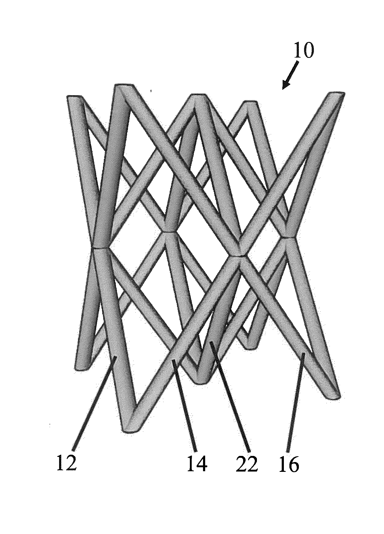
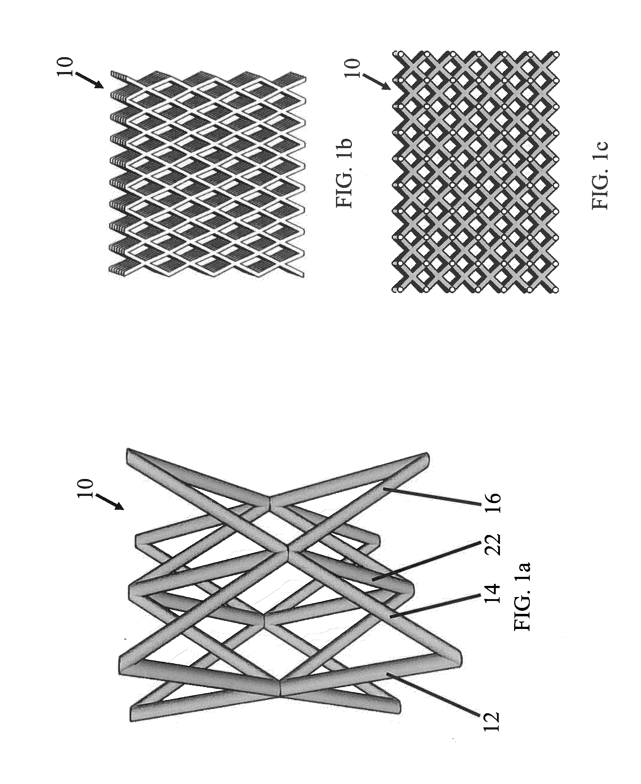
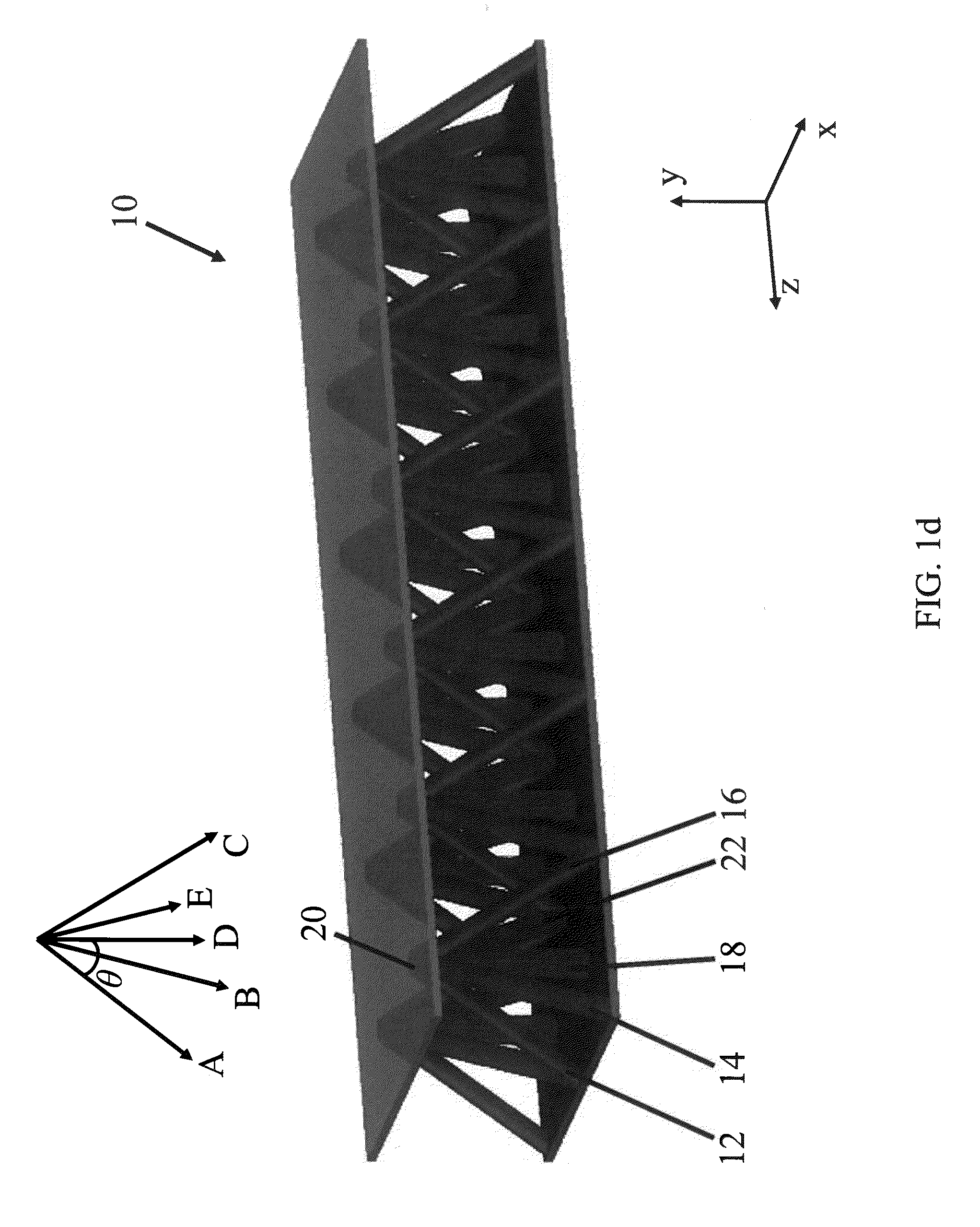
[0067]In the following detailed description, only certain exemplary embodiments of the present invention are shown and described, by way of illustration. As those skilled in the art would recognize, the invention may be embodied in many different forms and should not be construed as being limited to the embodiments set forth herein. Also, in the context of the present application, when an element is referred to as being “on” another element, it can be directly on the another element or be indirectly on the another element with one or more intervening elements interposed therebetween. Like reference numerals designate like elements throughout the specification.

[0068]Aspects of embodiments of the present invention are directed to an apparatus for maintaining an environmental state of a working surface. This environmental state can be provided, for example, by providing increased airflow to the working surface in contact with the apparatus. For example, aspects of embodiments of the pr...


PUM

PropertyMeasurementUnit
contact areaaaaaaaaaaa
diameteraaaaaaaaaa
diameteraaaaaaaaaa

Abstract

An apparatus for maintaining an environmental state of a working surface includes: a first micro-truss layer including: a plurality of first struts extending along a first direction; a plurality of second struts extending along a second direction; and a plurality of third struts extending along a third direction, the first, second, and third struts interpenetrating one another at a plurality of nodes, the first, second, and third struts interpenetrating one another at non-perpendicular angles, the apparatus having a contact surface configured to contact the working surface and having an open porosity configured to allow air to flow to the contact surface, wherein a total surface area of the contact surface is between about 1% and about 50% of a total surface area of the working surface.

Description

BACKGROUND[0001]1. Field[0002]The described technology relates generally to a micro-truss structure and the use of the micro-truss structure in a material or apparatus for controlling the environmental state of a working surface (e.g., a micro-truss perspiration control layer for controlling airflow to a human body).[0003]2. Description of Related Art[0004]A number of approaches currently exist on the market to improve air flow through structures or materials that are expected to have long-duration contact with some portion of a human or animal body, usually constituted from some kind of foam padding. Most often this padding is closed-cell foam. The most relevant of these approaches generally rely on manufacturing air flow pathways into the closed cell foam. Examples include shoe insoles with holes, “egg crate” foam padding, honeycomb materials, formed solid materials or open-cell foams, and thin stretched web-like or loose-weave fabrics.[0005]However, without significantly compromi...

Claims


Application Information

Patent Timeline
Patent Type & Authority Applications(United States)
IPC IPC(8): B32B3/26
CPCB32B5/028B32B5/24B32B3/12B32B2307/724B32B2437/02B32B2479/00B32B2605/00Y10T428/249953Y10T428/12347B32B3/26A43B13/18
Inventor JACOBSEN, ALAN J.CARTER, WILLIAMMANNING, SHA-CHELLE
Owner HRL LAB
Why Eureka
Try Eureka