
Large outboard motor including variable gear transfer case

a variable gear transfer and outboard motor technology, applied in the field of outboard motors, can solve the problems of high power system development limits, time-consuming, complicated, costly, etc., and achieve the effects of high quality, increased power output, and reduced cos

Active Publication Date: 2013-10-17
VOLVO PENTA AB
View PDF3 Cites 53 Cited by
  • Summary
  • Abstract
  • Description
  • Claims
  • Application Information

AI Technical Summary

Benefits of technology

The present invention relates to outboard motor marine propulsion systems. The inventors have recognized that the use of vertical crankshaft engines has limitations in terms of power output, so they have explored the possibility of using horizontal crankshaft engines, which can allow for the use of high-quality, relatively inexpensive engines and improve power output and other performance parameters. The use of three-part transmissions and exhaust conduits, as well as cooling mechanisms, can enhance the performance of outboard motor marine propulsion systems utilizing horizontal crankshaft engines. The mounting system by which the outboard motor is attached to the marine vessel can also be designed to take advantage of the use of a horizontal crankshaft engine.

Problems solved by technology

The present inventors have recognized that vertical crankshaft engines, which are naturally suited for outboard motor applications insofar as the crankshafts naturally are configured to deliver rotational power downward from the engines to the propellers situated at the bottoms of the outboard motors for interaction with the water, nevertheless impose serious limits on the development of higher power systems, because the development of vertical crankshaft engines capable of achieving substantial increases in power output in outboard motor marine propulsion systems has proven to be very time-consuming, complicated, and costly.

Method used


Image

  • Large outboard motor including variable gear transfer case
  • Large outboard motor including variable gear transfer case
  • Large outboard motor including variable gear transfer case

Examples


Embodiment Construction

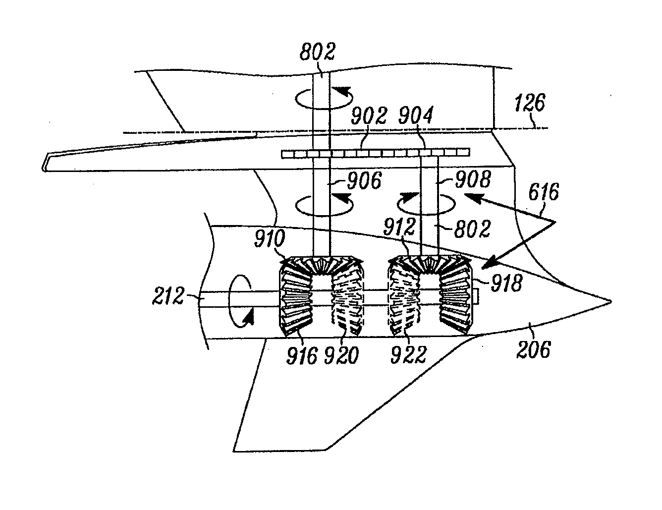
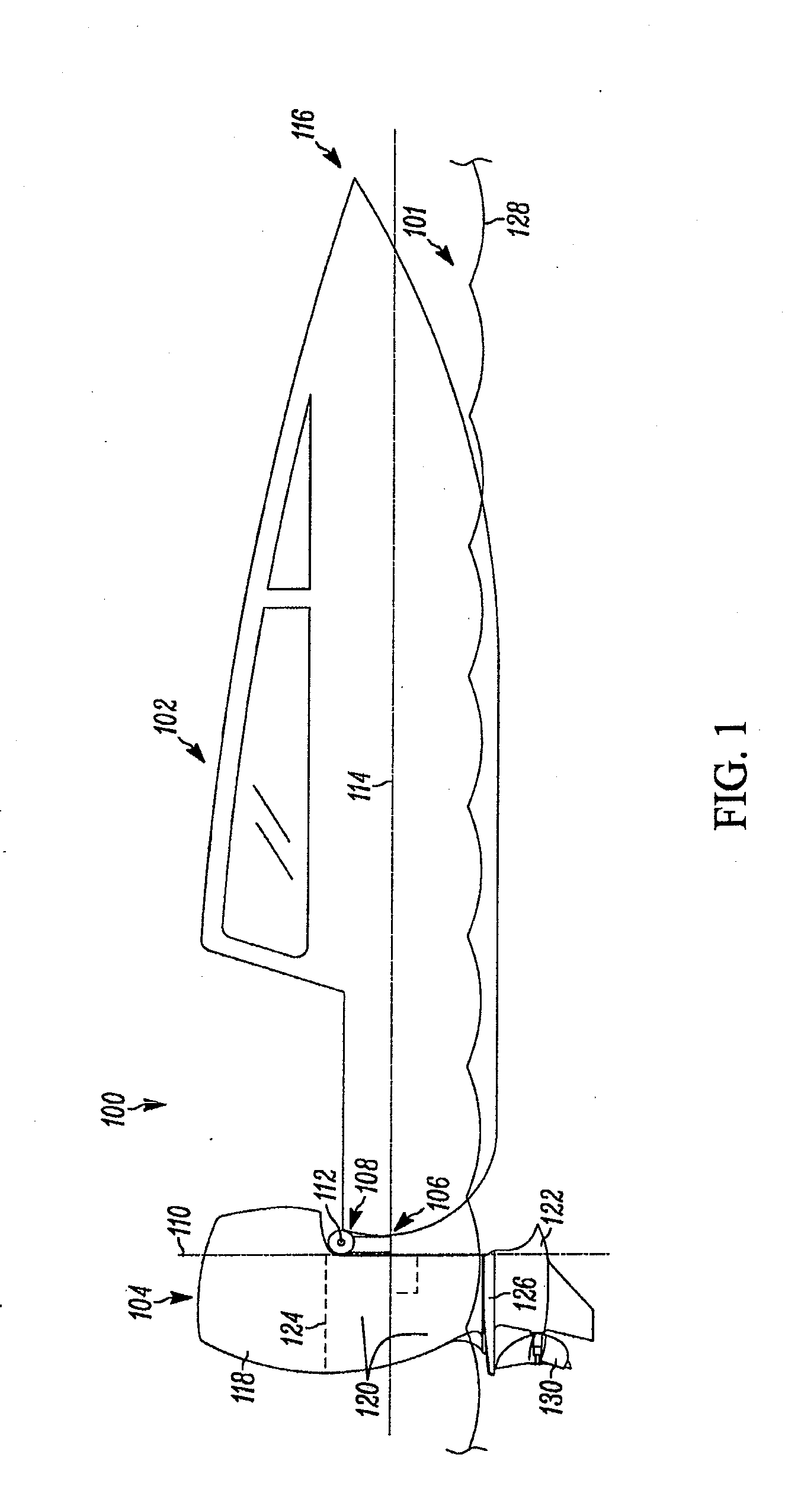
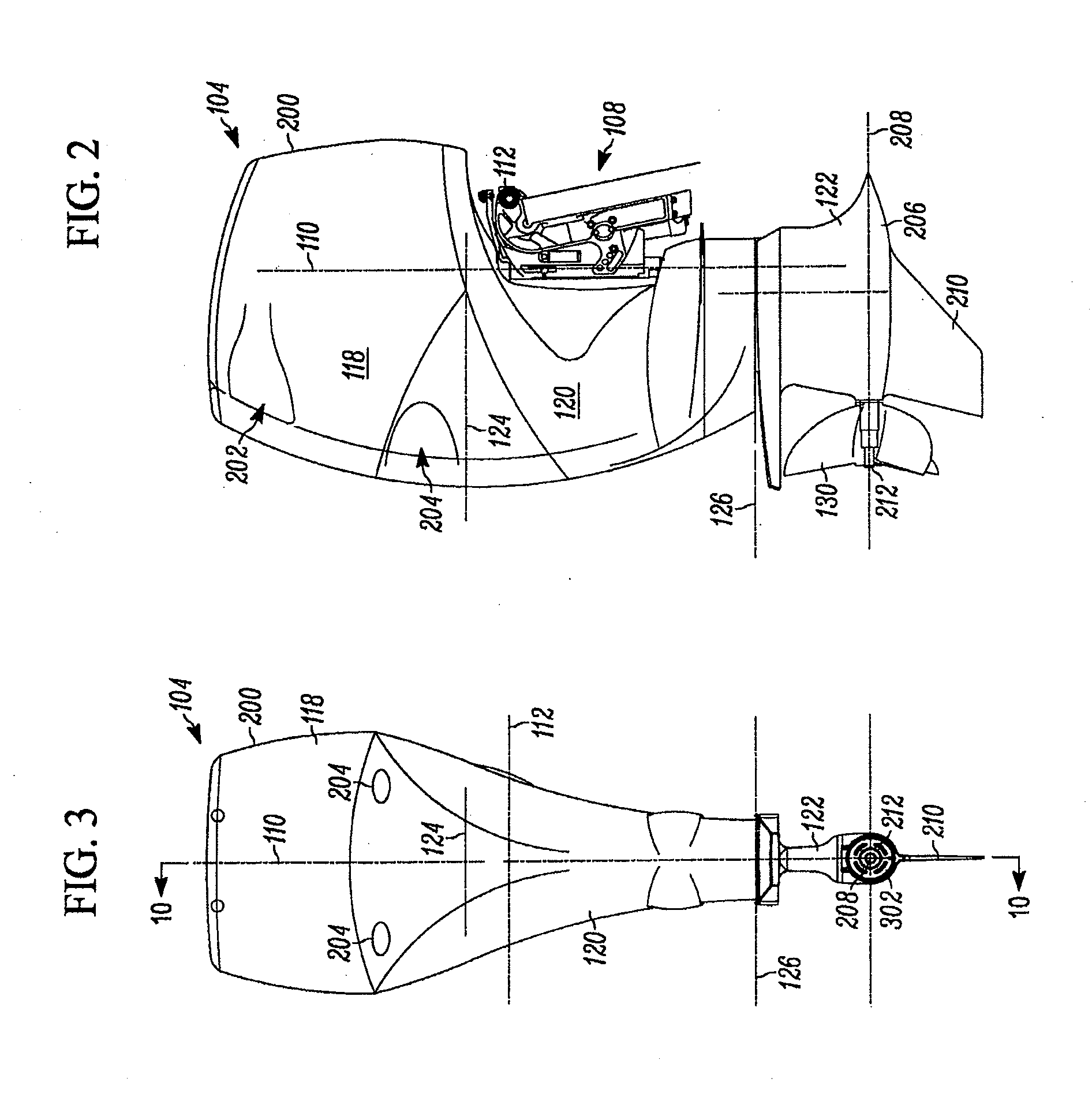
[0060]Referring to FIG. 1, an example marine vessel assembly 100 is shown to be floating in water 101 (shown in cut-away) that includes, in addition to an example marine vessel 102, an example outboard motor marine propulsion system 104, which for simplicity is referred to below more simply as an outboard motor 104. As shown, the outboard motor 104 is coupled to a stern (rear) edge or transom 106 of the marine vessel 102 by way of a mounting system 108, which is described in further detail below. Also described below, the mounting system 108 will be considered, for purposes of the present discussion, to be part of the outboard motor 104 although one or more components of the mounting system can technically be assembled directly to the stern edge (transom) 106 and thus could also be viewed as constituting part of the marine vessel 102 itself. In the present embodiment shown, the marine vessel 102 is shown to be a speed boat although, depending upon the embodiment, the marine vessel c...


PUM


Abstract

An outboard motor for a marine vessel application, transmission devices for such an outboard motor, and related methods of making, operating, and modifying attributes of same, are disclosed herein. In at least one embodiment, the motor includes a horizontal-crankshaft engine in an upper portion of the motor, positioned substantially above a trimming axis of the motor. In at least another embodiment, first, second and third transmission devices are employed to transmit rotational power from the engine to propeller(s). In at least a further embodiment, the motor is made to include a rigid interior assembly formed by the engine, multiple transmission devices, and a further structural component. In further embodiments, the motor includes numerous cooling, exhaust, and / or oil system components, and / or other transmission features. In at least some additional embodiments, a transmission device of the motor is configured to facilitate gear ratio variation and / or includes an integrated oil pump.

Description

CROSS-REFERENCE TO RELATED APPLICATIONS[0001]The present application claims the benefit of U.S. provisional patent application No. 61 / 623,530 filed on Apr. 12, 2012 and entitled “Large Outboard Motor Including Variable Gear Transfer Case”, which is hereby incorporated by reference herein.STATEMENT REGARDING FEDERALLY SPONSORED RESEARCH OR DEVELOPMENT[0002]--FIELD OF THE INVENTION[0003]The present invention relates to marine propulsion systems and / or related methods of making and / or operating such systems, and more particularly to outboard motors used as marine propulsion systems, alone and / or in combination with marine vessels with respect to which those motors are implemented, and / or methods of making and / or operating same.BACKGROUND OF THE INVENTION[0004]There exist currently many types of motorized or engine-driven propulsion systems for boats and other marine vehicles or vessels (collectively referred to herein generally as “marine vessels”). An inboard engine marine propulsion ...

Claims


Application Information

Patent Timeline
IPC IPC(8): B63H20/14B63H20/00
CPCB63H20/14B63H20/002B63H20/32B63H2020/323F16H57/031F16H57/0436F16H57/0441F16H2057/0075F16H2057/02043
Inventor DAVIS, ERIC A.DAVIS, RICHARD A.
Owner VOLVO PENTA AB
Learn More